Lexus ES: Removal
REMOVAL
CAUTION / NOTICE / HINT
The necessary procedures (adjustment, calibration, initialization, or registration) that must be performed after parts are removed and installed, or replaced during rear No. 1 differential mount cushion removal/installation are shown below.
Necessary Procedures After Parts Removed/Installed/Replaced| Replaced Part or Performed Procedure | Necessary Procedure | Effect/Inoperative Function when Necessary Procedure not Performed | Link |
|---|---|---|---|
| *1: for LED Type Turn Signal Light | |||
| Suspension, tires, etc. (The vehicle height changes because of suspension or tire replacement.) |
|
| |
| Rear television camera assembly optical axis adjustment (Back camera position setting) | Parking Assist Monitor System | | |
| Panoramic View Monitor System | | |
| Perform headlight ECU sub-assembly LH initialization*1 | Lighting System | | |
| Rear height control sensor sub-assembly LH | Perform headlight ECU sub-assembly LH initialization*1 | Lighting System | |
| Rear wheel alignment adjustment |
|
| |
| Exhaust system parts | Inspection after repair |
| |
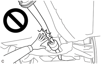
CAUTION:
To prevent burns, do not touch the engine, exhaust pipe or other high temperature components while the engine is hot.
PROCEDURE
1. REMOVE REAR DIFFERENTIAL CARRIER ASSEMBLY
Click here .gif)
2. REMOVE REAR NO. 1 DIFFERENTIAL MOUNT CUSHION
(a) Using SST, remove the rear No. 1 differential mount cushion.
SST: 09316-12010
SST: 09570-24011
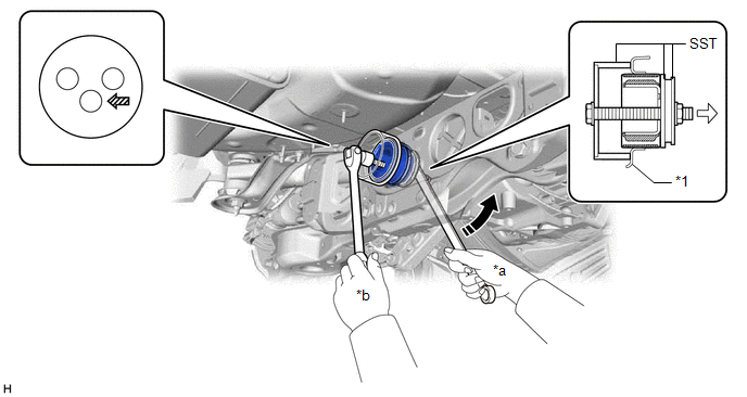
| *1 | Rear Suspension Member Sub-assembly | - | - |
| *a | Turn | *b | Hold |
.png) | Turning Direction | .png) | Front of Vehicle |
.png) | SST Bolt Position | - | - |
NOTICE:
- Do not bring SST into contact with the rear suspension member sub-assembly.
- Before using SST, apply grease to SST bolt.
- Set SST in the correct direction.
- Do not tilt the SST bolt.
- Do not reuse the rear No. 1 differential mount cushion.
READ NEXT:
 Differential Oil
ComponentsCOMPONENTS ILLUSTRATION *1 REAR DIFFERENTIAL FILLER PLUG *2 REAR DIFFERENTIAL DRAIN PLUG *3 GASKET - - N*m (kgf*cm, ft.*lbf): Specified torque ● Non-reusabl
Differential System
PrecautionPRECAUTION
Before disassembling the differential assembly, thoroughly clean it by removing any sand, mud or foreign matter. This will help prevent contamination during disassembly and re
SEE MORE:
High Voltage System Interlock Circuit Open (P0A0A13,P0A0A92)
DTC SUMMARY MALFUNCTION DESCRIPTION The hybrid vehicle control ECU detects that a safety device (interlock) is operated or that there is an open circuit in the detection circuit. (Even if an open circuit occurs while the vehicle is stopped, the system determines that the safety device was operated.)
Sensor (Motor) Failure (B2341,B2344)
DESCRIPTION When the sliding roof ECU (sliding roof drive gear sub-assembly) detects a motor malfunction and the sliding roof operation is stopped, DTC B2341 is stored. When the sliding roof ECU (sliding roof drive gear sub-assembly) detects a gear position malfunction and the sliding roof operation
