Lexus ES: Removal
REMOVAL
PROCEDURE
1. REMOVE FRONT DOOR SCUFF PLATE LH
Click here .gif)
2. REMOVE COWL SIDE TRIM BOARD LH
Click here
3. REMOVE FRONT DOOR OPENING TRIM COVER LH
Click here
4. REMOVE INSTRUMENT SIDE PANEL LH
Click here
5. REMOVE NO. 1 INSTRUMENT PANEL UNDER COVER SUB-ASSEMBLY
Click here
6. REMOVE LOWER INSTRUMENT PANEL FINISH PANEL SUB-ASSEMBLY
Click here
7. REMOVE NO. 1 INSTRUMENT CLUSTER MOULDING
Click here
8. REMOVE INSTRUMENT PANEL FINISH PANEL END LH
Click here
9. REMOVE LOWER INSTRUMENT PANEL
Click here
10. REMOVE FRONT DOOR SCUFF PLATE RH
HINT:
Use the same procedure as for the LH side.
11. REMOVE COWL SIDE TRIM BOARD RH
HINT:
Use the same procedure as for the LH side.
12. REMOVE FRONT DOOR OPENING TRIM COVER RH
HINT:
Use the same procedure as for the LH side.
13. REMOVE INSTRUMENT SIDE PANEL RH
Click here
14. REMOVE LOWER INSTRUMENT PANEL SUB-ASSEMBLY
Click here
15. REMOVE NO. 2 INSTRUMENT CLUSTER MOULDING
Click here
16. REMOVE AIR CONDITIONING CONTROL ASSEMBLY
Click here
17. REMOVE INSTRUMENT CLUSTER FINISH PANEL SUB-ASSEMBLY (w/o Headup Display)
Click here
18. REMOVE INSTRUMENT CLUSTER FINISH PANEL SUB-ASSEMBLY (w/ Headup Display)
Click here
19. REMOVE UPPER INSTRUMENT PANEL FINISH PANEL SUB-ASSEMBLY
Click here
20. REMOVE NO. 1 INSTRUMENT CLUSTER FINISH PANEL GARNISH
Click here
21. REMOVE INSTRUMENT CLUSTER FINISH PANEL ASSEMBLY
Click here
22. REMOVE SWITCH BASE
Click here
23. REMOVE ENGINE SWITCH
(a) Insert a screwdriver at the position shown in the illustration and detach the claw and remove the engine switch.
HINT:
Tape the screwdriver tip before use.
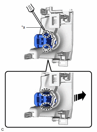
| *a | Protective Tape |
.png) | Insert Screwdriver Here |
.png) | Remove in this Direction |
READ NEXT:
 Inspection
INSPECTION PROCEDURE 1. INSPECT ENGINE SWITCH (a) Check the resistance. (1) Measure the resistance according to the value(s) in the table below. Standard Resistance: Tester Connection Conditi
Installation
INSTALLATION PROCEDURE 1. INSTALL ENGINE SWITCH (a) Attach the claw to install the engine switch as shown in the illustration. Install in this Direction 2. INSTALL SWITCH BASE Click here 3
Relay
InspectionINSPECTION PROCEDURE 1. INSPECT ST RELAY (a) Check the resistance. (1) Measure the resistance according to the value(s) in the table below. Standard Resistance: Tester Connection C
SEE MORE:
Fail-safe Chart
FAIL-SAFE CHART PROTECTION FUNCTION (a) The windshield wiper motor assembly operates the following protection functions if it detects an abnormal condition, in order to protect the wiper and washer system. Item Protection Content Conditions to Return to Normal Condition Overheat protectio
Components
COMPONENTS ILLUSTRATION *1 VACUUM HOSE *2 FLOW SHUTTING VALVE (NO. 1 WATER BY-PASS HOSE) *3 WATER BY-PASS HOSE ASSEMBLY *4 STEERING GEAR HEAT INSULATOR *5 WIRE HARNESS *6 FRONT FRAME ASSEMBLY *7 TRANSMISSION BREATHER CLAMP *8 HOSE CLAMP Tightening torqu
