Lexus ES: Removal
REMOVAL
CAUTION / NOTICE / HINT
The necessary procedures (adjustment, calibration, initialization or registration) that must be performed after parts are removed and installed, or replaced during fuel pump control ECU removal/installation are shown below.
Necessary Procedures After Parts Removed/Installed/Replaced| Replaced Part or Performed Procedure | Necessary Procedure | Effect/Inoperative Function when Necessary Procedure not Performed | Link |
|---|---|---|---|
|
*: When performing learning using the Techstream.
Click here | |||
| Battery terminal is disconnected/reconnected | Perform steering sensor zero point calibration | Lane Control System (for Gasoline Model) | |
| Pre-collision System (for Gasoline Model) | |||
| Parking Support Brake System (for Gasoline Model)* | |||
| Lighting System (for Gasoline Model) | |||
| Memorize steering angle neutral point | Parking Assist Monitor System (for Gasoline Model) | | |
| Panoramic View Monitor System (for Gasoline Model) | | ||
| Initialize power trunk lid system | Power Trunk Lid System (for Gasoline Model) | | |
NOTICE:
- After the engine switch is turned off, the radio receiver assembly records various types of memory and settings. As a result, after turning the engine switch off, make sure to wait at least 85 seconds before disconnecting the cable from the negative (-) battery terminal. (for Audio and Visual System)
- After the engine switch is turned off, the radio receiver assembly records various types of memory and settings. As a result, after turning the engine switch off, make sure to wait at least 85 seconds before disconnecting the cable from the negative (-) battery terminal. (for Navigation System)
PROCEDURE
1. REMOVE REAR SEAT ASSEMBLY
Click here .gif)
2. REMOVE REAR DOOR SCUFF PLATE LH
Click here
3. REMOVE REAR SEAT SIDE GARNISH LH
Click here
4. REMOVE FUEL PUMP CONTROL ECU
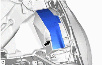
(a) w/ Silencer Sheet:
| (1) Remove the No. 2 room partition panel silencer sheet from the room partition panel insulator. |
|
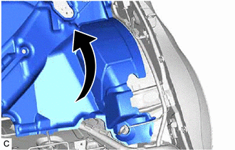
| (b) Turn back the room partition panel insulator. |
|
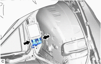
| (c) Disconnect the 2 fuel pump control ECU connectors. |
|
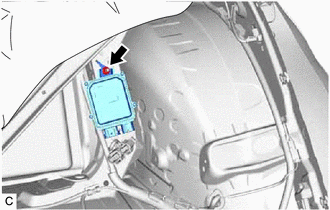
| (d) Remove the nut and fuel pump control ECU from the vehicle body. NOTICE: Do not reuse the fuel pump control ECU if it has been dropped or subjected to a severe impact. |
|
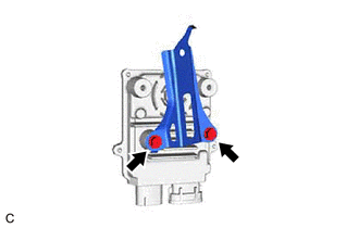
5. REMOVE FUEL PUMP CONTROL ECU BRACKET
| (a) Remove the 2 bolts and fuel pump control ECU bracket from the fuel pump control ECU. |
|
READ NEXT:
 Installation
INSTALLATION PROCEDURE 1. INSTALL FUEL PUMP CONTROL ECU BRACKET (a) Install the fuel pump control ECU bracket to the fuel pump control ECU with the 2 bolts. Torque: 4.5 N·m {46 kgf·cm, 40 in·lbf}
Components
COMPONENTS ILLUSTRATION *1 FUEL SUCTION PLATE SUB-ASSEMBLY *2 FUEL SENDER GAUGE ASSEMBLY *3 FUEL SUB-TANK - -
SEE MORE:
Back Camera Initialization Incomplete (C1691)
DESCRIPTION This DTC is stored when the rear television camera assembly judges that the back camera initial setting has not been memorized (rear television camera assembly optical axis adjustment (back camera position setting) is incomplete). DTC No. Detection Item DTC Detection Condition T
Reassembly
REASSEMBLY CAUTION / NOTICE / HINT HINT:
Use the same procedure for the RH side and LH side.
The following procedure is for the LH side.
PROCEDURE 1. INSTALL FRONT AXLE OUTBOARD JOINT BOOT (a) Secure the drive shaft in a vise between aluminum plates. NOTICE: Do not overtighten the vise. (
