Lexus ES: Removal
REMOVAL
PROCEDURE
1. REMOVE VACUUM SWITCHING VALVE (for Active Control Engine Mount System)
Click here .gif)
2. REMOVE FRONT WHEEL OPENING EXTENSION PAD RH
Click here
3. REMOVE FRONT WHEEL OPENING EXTENSION PAD LH
Click here
4. REMOVE NO. 1 ENGINE UNDER COVER
Click here
5. REMOVE NO. 2 ENGINE UNDER COVER ASSEMBLY
Click here
6. REMOVE SUSPENSION TOWER DAMPER (w/ Performance Damper)
Click here
7. REMOVE FRONT ENGINE MOUNTING INSULATOR
| (a) Disengage the 4 clamps to separate the radiator hose, vacuum hoses and No. 2 engine wire from the No. 1 radiator bracket. |
|
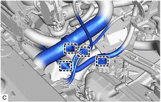
| (b) Remove the bolt and No. 1 radiator bracket from the front engine mounting bracket. |
|
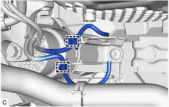
| (c) Disengage the 2 clamps to separate the vacuum hoses from the front engine mounting insulator. |
|
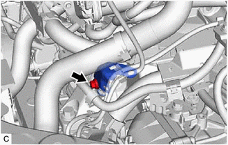
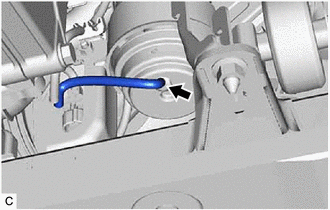
| (d) Remove the vacuum hose from the front engine mounting insulator. |
|
(e) Support the engine assembly with transaxle using a jack and wooden block.
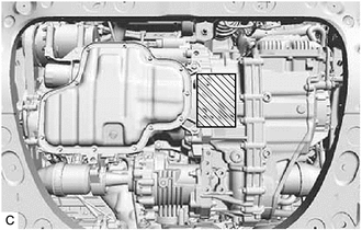
.png) | Wooden Block Placement Location |
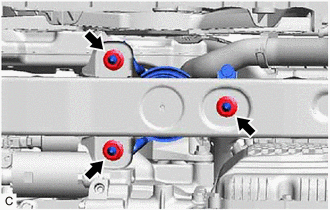
| (f) Remove the 4 bolts and front engine mounting bracket. |
|
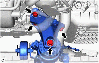
| (g) Remove the 3 nuts and front engine mounting insulator from the front frame assembly. |
|
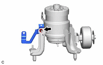
| (h) Remove the nut and stay from the front engine mounting insulator. |
|
READ NEXT:
 Installation
INSTALLATION PROCEDURE 1. INSTALL FRONT ENGINE MOUNTING INSULATOR (a) Install the stay to the front engine mounting insulator with the nut. Torque: 6.0 N·m {61 kgf·cm, 53 in·lbf} (b) Install the f
Removal
REMOVAL CAUTION / NOTICE / HINT The necessary procedures (adjustment, calibration, initialization or registration) that must be performed after parts are removed and installed, or replaced during air
SEE MORE:
On-vehicle Inspection
ON-VEHICLE INSPECTION PROCEDURE 1. INSPECT WINDSHIELD WIPER MOTOR ASSEMBLY (a) for RH Side (1) Operate the windshield wiper motor assembly. (2) Stop the windshield wiper motor assembly operation. (3) Check the automatic stop (park) position. HINT: After the front wiper motor is stopped, check the
Installation
INSTALLATION CAUTION / NOTICE / HINT HINT:
Use the same procedure for the RH side and LH side.
The following procedure is for the LH side.
PROCEDURE 1. PRECAUTION NOTICE: After turning the engine switch (for Gasoline Model) or power switch (for HV Model) off, waiting time may be required bef
