Lexus ES: Components
COMPONENTS
ILLUSTRATION
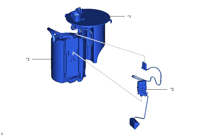
| *1 | FUEL SUCTION PLATE SUB-ASSEMBLY | *2 | FUEL SENDER GAUGE ASSEMBLY |
| *3 | FUEL SUB-TANK | - | - |
READ NEXT:
 Removal
REMOVAL CAUTION / NOTICE / HINT The necessary procedures (adjustment, calibration, initialization or registration) that must be performed after parts are removed and installed, or replaced during fuel
Inspection
INSPECTION PROCEDURE 1. INSPECT FUEL SENDER GAUGE ASSEMBLY CAUTION: Perform the inspection in a well-ventilated area. Do not perform the inspection near an open flame. (a) Check that the float moves s
Installation
INSTALLATION PROCEDURE 1. INSTALL FUEL SENDER GAUGE ASSEMBLY (a) Engage the claw to install the fuel sender gauge assembly to the fuel sub-tank. NOTICE: Be careful not to bend the arm of the fuel send
SEE MORE:
Back-up Light Circuit
DESCRIPTION The hybrid vehicle control ECU controls the back-up lights via the BKUP LP relay. WIRING DIAGRAM CAUTION / NOTICE / HINT NOTICE:
Inspect the fuses for circuits related to this system before performing the following procedure.
Before replacing the hybrid vehicle control ECU, refer t
Repair
REPAIR CAUTION / NOTICE / HINT HINT:
Use the same procedure for bank 1 and bank 2.
The following procedure is for bank 2.
PROCEDURE 1. REPAIR INTAKE VALVE SEAT NOTICE:
While repairing the intake valve seat, make sure to constantly check the valve seat width and valve seating position.
R
© 2016-2026 Copyright www.lexguide.net
