Lexus ES: Open in Bus 4 Main Bus Line
DESCRIPTION
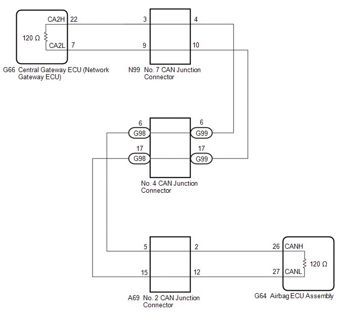
There may be an open circuit in one of the CAN main bus lines when the resistance between terminals 22 (CA2H) and 7 (CA2L) of the central gateway ECU (network gateway ECU) is 70 Ω or higher.
| Symptom | Trouble Area |
|---|---|
| Resistance between terminals 22 (CA2H) and 7 (CA2L) of the central gateway ECU (network gateway ECU) is 70 Ω or higher. |
|
This malfunction is not related to the lines of a CAN branch or to ECUs or sensors connected to a CAN branch.
WIRING DIAGRAM
CAUTION / NOTICE / HINT
CAUTION:
When performing the confirmation driving pattern, obey all speed limits and traffic laws.
NOTICE:
-
Because the order of diagnosis is important to allow correct diagnosis, make sure to begin troubleshooting using How to Proceed with Troubleshooting when CAN communication system related DTCs are output.
Click here
.gif)
- Before measuring the resistance of the CAN bus, turn the power switch off and leave the vehicle for 1 minute or more without operating the key or any switches, or opening or closing the doors. After that, disconnect the cable from the negative (-) auxiliary battery terminal and leave the vehicle for 1 minute or more before measuring the resistance.
-
After turning the power switch off, waiting time may be required before disconnecting the cable from the negative (-) auxiliary battery terminal. Therefore, make sure to read the disconnecting the cable from the negative (-) auxiliary battery terminal notices before proceeding with work.
Click here
-
After performing repairs, perform the DTC check procedure and confirm that the DTCs are not output again.
DTC check procedure: Turn the power switch on (IG) and wait for 1 minute or more. Then operate the suspected malfunctioning system and drive the vehicle at 60 km/h (37 mph) or more for 5 minutes or more.
-
After the repair, perform the CAN bus check and check that all the ECUs and sensors connected to the CAN communication system are displayed as normal.
Click here
HINT:
- Before disconnecting related connectors for inspection, push in on each connector body to check that the connector is not loose or disconnected.
- When a connector is disconnected, check that the terminals and connector body are not cracked, deformed or corroded.
PROCEDURE
| 1. | CHECK FOR OPEN IN CAN MAIN BUS LINES (NO. 7 CAN JUNCTION CONNECTOR) |
(a) Disconnect the cable from the negative (-) auxiliary battery terminal.
(b) Disconnect the N99 No. 7 CAN junction connector.
(c) Measure the resistance according to the value(s) in the table below.
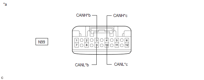
| *a | Front view of wire harness connector (to No. 7 CAN Junction Connector) | *b | to Central Gateway ECU (Network Gateway ECU) |
| *c | to No. 4 CAN Junction Connector | - | - |
Standard Resistance:
| Tester Connection | Condition | Specified Condition | Connected to |
|---|---|---|---|
| N99-3 (CANH) - N99-9 (CANL) | Cable disconnected from negative (-) auxiliary battery terminal | 108 to 132 Ω | Central gateway ECU (network gateway ECU) |
| N99-4 (CANH) - N99-10 (CANL) | Cable disconnected from negative (-) auxiliary battery terminal | 108 to 132 Ω | No. 4 CAN junction connector |
| Result | Proceed to |
|---|---|
| OK | A |
| NG (Line to central gateway ECU (network gateway ECU)) | B |
| NG (Line to No. 4 CAN junction connector) | C |
| A | .gif) | REPLACE NO. 7 CAN JUNCTION CONNECTOR |
| C | | GO TO STEP 3 |
|
.gif)
| 2. | CHECK FOR OPEN IN CAN MAIN BUS LINES (CENTRAL GATEWAY ECU (NETWORK GATEWAY ECU)) |
(a) Reconnect the N99 No. 7 CAN junction connector.
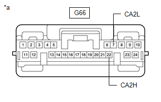
(b) Disconnect the G66 central gateway ECU (network gateway ECU) connector.
| (c) Measure the resistance according to the value(s) in the table below. Standard Resistance:
|
|
| OK | | REPLACE CENTRAL GATEWAY ECU (NETWORK GATEWAY ECU) |
| NG | | REPAIR OR REPLACE CAN MAIN BUS LINES OR CONNECTOR (CENTRAL GATEWAY ECU (NETWORK GATEWAY ECU) - NO. 7 CAN JUNCTION CONNECTOR) |
| 3. | CHECK FOR OPEN IN CAN MAIN BUS LINES (NO. 4 CAN JUNCTION CONNECTOR - NO. 7 CAN JUNCTION CONNECTOR) |
(a) Reconnect the N99 No. 7 CAN junction connector.
(b) Disconnect the G99 No. 4 CAN junction connector.
(c) Measure the resistance according to the value(s) in the table below.
.png)
| *a | Front view of wire harness connector (to No. 4 CAN Junction Connector) | *b | to No. 7 CAN Junction Connector |
Standard Resistance:
| Tester Connection | Condition | Specified Condition |
|---|---|---|
| G99-6 (CANH) - G99-17 (CANL) | Cable disconnected from negative (-) auxiliary battery terminal | 108 to 132 Ω |
| NG | | REPAIR OR REPLACE CAN MAIN BUS LINES OR CONNECTOR (NO. 4 CAN JUNCTION CONNECTOR - NO. 7 CAN JUNCTION CONNECTOR) |
|
| 4. | CHECK FOR OPEN IN CAN MAIN BUS LINES (NO. 4 CAN JUNCTION CONNECTOR) |
(a) Reconnect the G99 No. 4 CAN junction connector.
(b) Disconnect the G98 No. 4 CAN junction connector.
(c) Measure the resistance according to the value(s) in the table below.
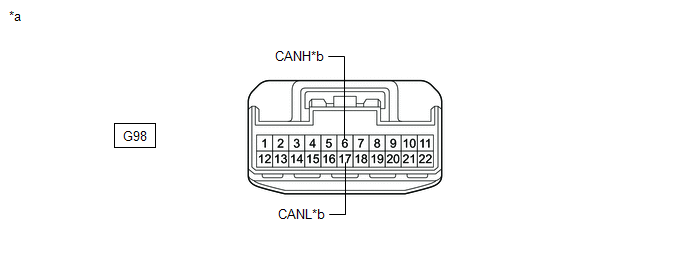
| *a | Front view of wire harness connector (to No. 4 CAN Junction Connector) | *b | to No. 2 CAN Junction Connector |
Standard Resistance:
| Tester Connection | Condition | Specified Condition |
|---|---|---|
| G98-6 (CANH) - G98-17 (CANL) | Cable disconnected from negative (-) auxiliary battery terminal | 108 to 132 Ω |
| OK | | REPLACE NO. 4 CAN JUNCTION CONNECTOR |
|
| 5. | CHECK FOR OPEN IN CAN MAIN BUS LINES (NO. 2 CAN JUNCTION CONNECTOR) |
(a) Reconnect the G98 No. 4 CAN junction connector.
(b) Disconnect the A69 No. 2 CAN junction connector.
(c) Measure the resistance according to the value(s) in the table below.
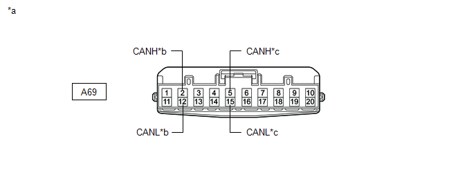
| *a | Front view of wire harness connector (to No. 2 CAN Junction Connector) | *b | to Airbag ECU Assembly |
| *c | to No. 4 CAN Junction Connector | - | - |
Standard Resistance:
| Tester Connection | Condition | Specified Condition | Connected to |
|---|---|---|---|
| A69-2 (CANH) - A69-12 (CANL) | Cable disconnected from negative (-) auxiliary battery terminal | 108 to 132 Ω | Airbag ECU assembly |
| A69-5 (CANH) - A69-15 (CANL) | Cable disconnected from negative (-) auxiliary battery terminal | 108 to 132 Ω | No. 4 CAN junction connector |
| Result | Proceed to |
|---|---|
| OK | A |
| NG (Line to airbag ECU assembly) | B |
| NG (Line to No. 4 CAN junction connector) | C |
| A | | REPLACE NO. 2 CAN JUNCTION CONNECTOR |
| C | | REPAIR OR REPLACE CAN MAIN BUS LINES OR CONNECTOR (NO. 2 CAN JUNCTION CONNECTOR - NO. 4 CAN JUNCTION CONNECTOR) |
|
| 6. | CHECK FOR OPEN IN CAN MAIN BUS LINES (AIRBAG ECU ASSEMBLY - NO. 2 CAN JUNCTION CONNECTOR) |
(a) Reconnect the A69 No. 2 CAN junction connector.
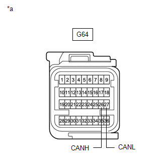
(b) Disconnect the G64 airbag ECU assembly connector.
| (c) Measure the resistance according to the value(s) in the table below. Standard Resistance:
|
|
| OK | | REPLACE AIRBAG ECU ASSEMBLY |
| NG | | REPAIR OR REPLACE CAN MAIN BUS LINES OR CONNECTOR (AIRBAG ECU ASSEMBLY - NO. 2 CAN JUNCTION CONNECTOR) |
READ NEXT:
 Open in One Side of Bus 3 Branch Line
DESCRIPTION When the CAN bus main lines are normal (no open, short to ground, short to +B or short between lines) and there is an ECU or sensor on the "Communication Bus Check" screen that is indicate
Check Bus 3 Line for Short to GND
DESCRIPTION There may be a short circuit between one of the CAN bus lines and GND when there is no resistance between terminal 6 (CA3H) of the central gateway ECU (network gateway ECU) and terminal 4
Check Bus 3 Line for Short to +B
DESCRIPTION There may be a short circuit between one of the CAN bus lines and +B when there is no resistance between terminal 6 (CA3H) of the central gateway ECU (network gateway ECU) and terminal 16
SEE MORE:
Brake System Control Module "A" System Internal Failure (C059704)
DESCRIPTION The skid control ECU (brake actuator assembly) stores this DTC if malfunctions are found in a circuit inside the ECU by self diagnosis. DTC No. Detection Item DTC Detection Condition Trouble Area C059704 Brake System Control Module "A" System Internal Failure Internal fa
Thermostat Heater Control Circuit Short to Ground or Open (P059714)
DESCRIPTION Refer to DTC P059712. Click here DTC No. Detection Item DTC Detection Condition Trouble Area MIL Memory Note P059714 Thermostat Heater Control Circuit Short to Ground or Open Open or short in thermostat heater circuit and power supply circuit (1 trip detection lo
