Lexus ES: Removal
REMOVAL
PROCEDURE
1. REMOVE NO. 1 INSTRUMENT PANEL UNDER COVER SUB-ASSEMBLY
Click here .gif)
2. REMOVE ACCELERATOR PEDAL(W/SENSOR) ROD ASSEMBLY
NOTICE:
- Avoid physical shock to the accelerator pedal sensor assembly.
- Do not disassemble the accelerator pedal sensor assembly.
- The accelerator pedal sensor assembly does not require lubrication.
- Do not apply oil or other lubricants to the accelerator pedal sensor assembly. If applied, the accelerator pedal sensor assembly must be replaced.
| (a) Disconnect the accelerator pedal sensor assembly connector. |
|
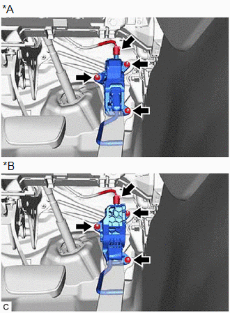
(b) Remove the 3 nuts and disconnect the rod of the accelerator pedal sensor assembly from the accelerator pedal assembly to remove the accelerator pedal sensor assembly.
NOTICE:
If the accelerator pedal sensor assembly has been struck or dropped, replace it.
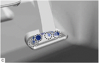
3. REMOVE ACCELERATOR PEDAL PAD
| (a) Disengage the 4 claws and remove the accelerator pedal pad from the accelerator pedal assembly. |
|
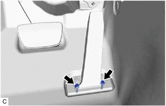
4. REMOVE ACCELERATOR PEDAL ASSEMBLY
| (a) Remove the 2 bolts. |
|
(b) Push the accelerator pedal assembly in the direction indicated by the arrow (1) shown in the illustration to disengage the claw.
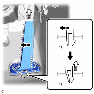
| *a | Vehicle Body |
 | Remove in this Direction (1) |
 | Remove in this Direction (2) |
(c) Pull the accelerator pedal assembly in the direction indicated by the arrow (2) shown in the illustration to remove it.
READ NEXT:
 Installation
INSTALLATION PROCEDURE 1. INSTALL ACCELERATOR PEDAL ASSEMBLY (a) Engage the claw to install the accelerator pedal assembly. (b) Install the 2 bolts. Torque: 7.5 N·m {76 kgf·cm, 66 in
Components
COMPONENTS ILLUSTRATION *A Type A *B Type B *1 FRONT WHEEL OPENING EXTENSION PAD LH *2 FRONT WHEEL OPENING EXTENSION PAD RH *3 NO. 1 ENGINE UNDER COVER *4 NO. 3 ENGINE UN
SEE MORE:
Oil And Oil Filter
ComponentsCOMPONENTS ILLUSTRATION *1 CENTER NO. 4 ENGINE UNDER COVER - - ILLUSTRATION *1 OIL FILTER SUB-ASSEMBLY *2 OIL FILLER CAP SUB-ASSEMBLY *3 GASKET *4 OIL PAN DRAIN PLUG Tightening torque for "Major areas involving basic vehicle performance such as movi
Removal
REMOVAL CAUTION / NOTICE / HINT The necessary procedures (adjustment, calibration, initialization or registration) that must be performed after parts are removed and installed, or replaced during fuel sender gauge assembly removal/installation are shown below. Necessary Procedures After Parts Remove
