Lexus ES: Removal
REMOVAL
CAUTION / NOTICE / HINT
The necessary procedures (adjustment, calibration, initialization or registration) that must be performed after parts are removed and installed, or replaced during water inlet with thermostat sub-assembly removal/installation are shown below.
Necessary Procedure After Parts Removed/Installed/Replaced| Replaced Part or Performed Procedure | Necessary Procedure | Effect/Inoperative Function when Necessary Procedure not Performed | Link |
|---|---|---|---|
| Battery terminal is disconnected/reconnected | Perform steering sensor zero point calibration | Lane Control System | |
| Pre-collision System | |||
| Parking Support Brake System*1 | |||
| Lighting System | |||
| Memorize steering angle neutral point | Parking Assist Monitor System | | |
| Panoramic View Monitor System | | ||
| Initialize power trunk lid system | Power Trunk Lid System | | |
| Replacement of ECM | Vehicle Identification Number (VIN) registration | MIL comes on | |
| ECU communication ID registration (Immobiliser system) | Engine start function | | |
| Gas leak from exhaust system is repaired | Inspection after repair |
| |
| Replacement of automatic transaxle assembly |
|
| for Initialization: for Registration: |
| Replacement of ECM (If transaxle compensation code read from ECM) |
| ||
| Replacement of ECM (If transaxle compensation code not read from ECM) |
| ||
| Replacement of ECM | Code registration (Smart access system with push-button start (for Start Function, Gasoline Model) |
| |
| Replacement of automatic transaxle fluid | ATF thermal degradation estimate reset | The value of the Data List item "ATF Thermal Degradation Estimate" is not estimated correctly | |
| Suspension, tires, etc. (The vehicle height changes because of suspension or tire replacement) | Rear television camera assembly optical axis adjustment (Back camera position setting) | Parking assist monitor system | for Initialization: for Calibration: |
| Perform headlight ECU sub-assembly LH initialization | Lighting system | | |
| Front wheel alignment adjustment |
|
| |
-
*1: When performing learning using the Techstream.
Click here
.gif)
- *2: Not necessary when ECM replaced with new one
NOTICE:
- After the engine switch is turned off, the radio receiver assembly records various types of memory and settings. As a result, after turning the engine switch off, make sure to wait at least 85 seconds before disconnecting the cable from the negative (-) battery terminal. (for Audio and Visual System)
- After the engine switch is turned off, the radio receiver assembly records various types of memory and settings. As a result, after turning the engine switch off, make sure to wait at least 85 seconds before disconnecting the cable from the negative (-) battery terminal. (for Navigation System)
PROCEDURE
1. REMOVE ENGINE ASSEMBLY WITH TRANSAXLE
Click here
2. REMOVE NO. 2 ENGINE MOUNTING STAY RH
| (a) Remove the bolt and disconnect the wire harness clamp from the wire harness clamp bracket. |
|
| (b) Remove the bolt and separate the wire harness clamp bracket from the No. 2 engine mounting stay RH. |
|
| (c) Remove the bolt and No. 2 engine mounting stay RH from the intake manifold and front No. 1 engine mounting bracket LH. |
|
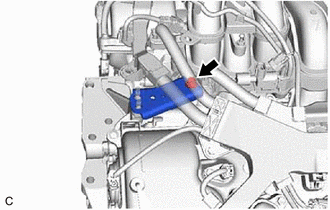
3. DISCONNECT ENGINE WIRE
| (a) Disconnect the water inlet with thermostat sub-assembly connector. |
|
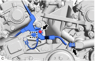
(b) Remove the bolt.
(c) Disengage the clamp to disconnect the engine wire.
4. REMOVE FRONT NO. 1 ENGINE MOUNTING BRACKET LH
Click here
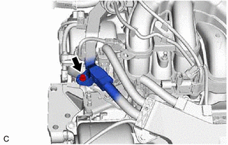
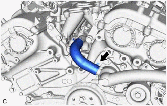
5. DISCONNECT WATER BY-PASS HOSE
| (a) Slide the clip and disconnect the water by-pass hose. |
|
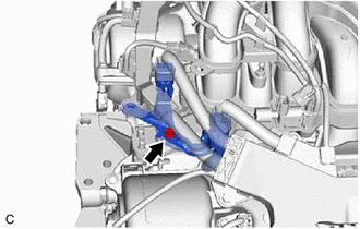
6. REMOVE WATER INLET WITH THERMOSTAT SUB-ASSEMBLY
| (a) Remove the 2 bolts, 2 nuts and water inlet with thermostat sub-assembly. |
|
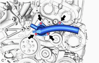
(b) Remove the gasket from the water inlet with thermostat sub-assembly.
READ NEXT:
 Inspection
INSPECTION PROCEDURE 1. INSPECT WATER INLET WITH THERMOSTAT SUB-ASSEMBLY (a) Check the valve opening. HINT: The valve opening temperature is inscribed on the water inlet with thermostat sub-assembly.
Installation
INSTALLATION PROCEDURE 1. INSTALL WATER INLET WITH THERMOSTAT SUB-ASSEMBLY (a) Install a new gasket to the water inlet with thermostat sub-assembly. (b) Install the water inlet with thermostat sub-ass
SEE MORE:
Components
COMPONENTS ILLUSTRATION *1 TRANSMISSION VALVE BODY ASSEMBLY *2 TRANSAXLE CASE GASKET *3 NO. 1 FRONT OIL PUMP COVER GASKET *4 NO. 2 FRONT OIL PUMP COVER GASKET Tightening torque for "Major areas involving basic vehicle performance such as moving/turning/stopping": N*m (kgf*
Steering Sensor Signal Malfunction (C1784)
DESCRIPTION Steering sensor signals are sent to the absorber control ECU via CAN communication. If a communication error is detected, DTC C1784 is stored. DTC No. Detection Item DTC Detection Condition Trouble Area Warning Indicate Memory C1784 Steering Sensor Signal Malfunction
