Lexus ES: Inspection
INSPECTION
PROCEDURE
1. INSPECT WATER INLET WITH THERMOSTAT SUB-ASSEMBLY
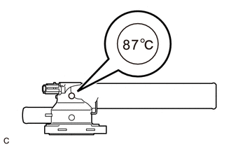
(a) Check the valve opening.
HINT:
The valve opening temperature is inscribed on the water inlet with thermostat sub-assembly.
| (1) Add 15 cc (0.9 cu. in.) of water to the water inlet with thermostat sub-assembly from the inlet pipe side. |
|
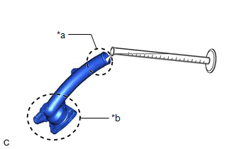
(2) Confirm that water does not flow out from the valve side of the water inlet with thermostat sub-assembly.
If water flows out from the valve side of the water inlet with thermostat sub-assembly, replace the water inlet with thermostat sub-assembly with a new one.
(3) Immerse the water inlet with thermostat sub-assembly in water that is between 92°C (198°F) and 96°C (205°F) for 5 minutes or more.
NOTICE:
- Do not allow any water to come into contact with the connector of the water inlet with thermostat sub-assembly.
- Make sure that the end of the inlet pipe of the water inlet with thermostat sub-assembly is not facing downward.
- Make sure to immerse the water inlet with thermostat sub-assembly in the water as shown in the illustration.
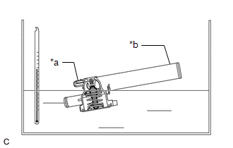
| *a | Connector |
| *b | Inlet Pipe |
 | Temperature Sensor |
| (4) Leave the water inlet with thermostat sub-assembly at ambient temperature for 5 minutes so that the valve closes. NOTICE: Make sure that the end of the inlet pipe of the water inlet with thermostat sub-assembly is not facing downward. |
|
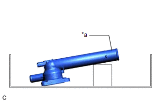
(5) Check that the water that was added to the water inlet with thermostat sub-assembly has completely flowed out.
If the water that was added to the water inlet with thermostat sub-assembly has not completely flowed out, replace the water inlet with thermostat sub-assembly with a new one.
(b) Check the resistance of the temperature sensor.
(1) Measure the resistance according to the value(s) in the table below.
Standard Resistance:
| Tester Connection | Condition | Specified Condition |
|---|---|---|
| 1 - 2 | Always | 10.6 to 14.2 Ω |
If the result is not as specified, replace the water inlet with thermostat sub-assembly.
READ NEXT:
 Installation
INSTALLATION PROCEDURE 1. INSTALL WATER INLET WITH THERMOSTAT SUB-ASSEMBLY (a) Install a new gasket to the water inlet with thermostat sub-assembly. (b) Install the water inlet with thermostat sub-ass
Components
COMPONENTS ILLUSTRATION *1 ENGINE WATER PUMP ASSEMBLY *2 NO. 2 IDLER PULLEY SUB-ASSEMBLY *3 WATER PUMP PULLEY *4 WATER PUMP GASKET *5 V-RIBBED BELT - - N*m (kgf*cm
SEE MORE:
Engine Coolant Temperature / Intake Air Temperature Signal Compare Failure (P011B62)
DESCRIPTION The engine has two temperature sensors, an engine coolant temperature sensor and an intake air temperature sensor (for mass air flow meter sub-assembly), to detect temperature while the engine is operating. A thermistor, whose resistance value varies according to the temperature, is buil
Lost Communication with Haptic Device (B1323-B1326)
DESCRIPTION These DTCs are stored when communication between the radio receiver assembly and remote touch (remote operation controller assembly), combination meter assembly, headup display (meter mirror sub-assembly)* or clock assembly is not possible.
*: w/ Headup Display System
DTC No.
