Lexus ES: Removal
REMOVAL
CAUTION / NOTICE / HINT
The necessary procedures (adjustment, calibration, initialization or registration) that must be performed after parts are removed and installed, or replaced during transmission wire removal/installation are shown below.
Necessary Procedures After Parts Removed/Installed/Replaced| Replaced Part or Performed Procedure | Necessary Procedure | Effect/Inoperative Function when Necessary Procedure not Performed | Link |
|---|---|---|---|
| Replacement of automatic transaxle fluid | ATF thermal degradation estimate reset | The value of the Data List item "ATF Thermal Degradation Estimate" is not estimated correctly | |
PROCEDURE
1. REMOVE FRONT WHEEL LH
Click here .gif)
2. REMOVE FRONT WHEEL OPENING EXTENSION PAD LH
Click here
3. REMOVE FRONT WHEEL OPENING EXTENSION PAD RH
Click here
4. REMOVE NO. 1 ENGINE UNDER COVER
Click here
5. REMOVE NO. 3 ENGINE UNDER COVER
Click here
6. REMOVE FRONT FENDER APRON SEAL LH
Click here
7. DRAIN AUTOMATIC TRANSAXLE FLUID
| (a) Remove the refill plug and gasket from the automatic transaxle case sub-assembly. |
|
.png)
| (b) Using a 10 mm hexagon socket wrench, remove the overflow plug and gasket from the transaxle housing. |
|
.png)
| (c) Using a 6 mm hexagon socket wrench, remove the No. 1 transmission oil filler tube from the transaxle housing and drain the automatic transaxle fluid. |
|
.png)
(d) Using a 6 mm hexagon socket wrench, install the No. 1 transmission oil filler tube to the transaxle housing.
Torque:
1.7 N·m {17 kgf·cm, 15 in·lbf}
(e) Using a 10 mm hexagon socket wrench, temporarily install the gasket and overflow plug to the transaxle housing.
HINT:
Reuse the old gasket as the overflow plug will be removed again to adjust the automatic transaxle fluid level.
(f) Temporarily install the gasket and refill plug to avoid automatic transaxle fluid spillage.
HINT:
Reuse the old gasket as the refill plug will be removed again to adjust the automatic transaxle fluid level.
8. REMOVE FRONT ENGINE MOUNTING INSULATOR
Click here
9. REMOVE FRONT SUSPENSION MEMBER DYNAMIC DAMPER
Click here
10. SEPARATE OIL COOLER UNION SUB-ASSEMBLY
| (a) Remove the bolt to separate the oil cooler union sub-assembly bracket portion from the automatic transaxle case sub-assembly. |
|
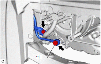
(b) Remove the oil cooler union bolt and 2 gaskets to separate the oil cooler union sub-assembly from the automatic transaxle case sub-assembly.
11. REMOVE TRANSMISSION CASE SIDE COVER
| (a) Remove the 10 bolts and transmission case side cover from the automatic transaxle case sub-assembly. |
|
.png)
12. REMOVE TRANSMISSION WIRE
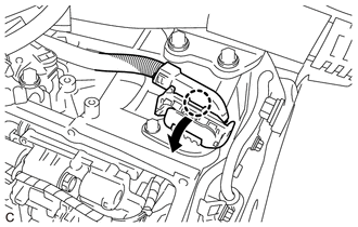
| (a) Disengage the claw, rotate the lever and disconnect the transmission wire connector. |
|
| (b) Disengage the clamp to disconnect the transmission wire from the solenoid lock plate. |
|
.png)
(c) Disconnect the 9 solenoid valve connectors.
HINT:
- Using a screwdriver, disconnect the solenoid valve connector (A) using the procedure shown in the illustration.
- Using a screwdriver, disconnect the solenoid valve connector (B) using the procedure shown in the illustration.
| (d) Remove the bolt and temperature sensor clamp and disconnect the temperature sensor from the transmission valve body assembly. |
|
.png)
| (e) Disconnect the transmission revolution sensor (NT) connector and transmission revolution sensor (NC) connector. |
|
.png)
| (f) Remove the bolt and transmission wire from the automatic transaxle case sub-assembly. |
|
.png)
READ NEXT:
 Components
COMPONENTS ILLUSTRATION *1 TRANSMISSION VALVE BODY ASSEMBLY *2 TRANSAXLE CASE GASKET *3 NO. 1 FRONT OIL PUMP COVER GASKET *4 NO. 2 FRONT OIL PUMP COVER GASKET Tightening tor
Disassembly
DISASSEMBLY PROCEDURE 1. REMOVE MANUAL VALVE (a) Remove the manual valve from the transmission valve body assembly. 2. REMOVE SOLENOID LOCK PLATE (a) Remove the 3 bolts and solenoid
SEE MORE:
Parts Location
PARTS LOCATION ILLUSTRATION *1 DEICER RELAY *2 NO. 2 ENGINE ROOM RELAY BLOCK AND NO. 2 ENGINE ROOM JUNCTION BLOCK ASSEMBLY - DEICER FUSE *3 MULTI-DISPLAY ASSEMBLY - FRONT WIPER DEICER SWITCH *4 WINDSHIELD DEICER WIRE (WINDSHIELD GLASS) *5 DLC3 *6 AIR CONDITIONING AMPLIF
Installation
INSTALLATION PROCEDURE 1. INSTALL HYBRID BATTERY TERMINAL BLOCK CAUTION: Be sure to wear insulated gloves and protective goggles. (a) Connect the 2 hybrid battery terminal block connectors. NOTICE: Make sure that the connectors are connected securely. (b) Install the hybrid battery terminal block
