Lexus ES: Radio Receiver Power Source Circuit
DESCRIPTION
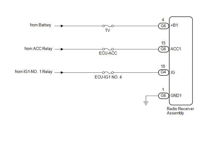
This is the power source circuit to operate the radio receiver assembly.
WIRING DIAGRAM
CAUTION / NOTICE / HINT
NOTICE:
Inspect the fuses for circuits related to this system before performing the following procedure.
PROCEDURE
| 1. | CHECK HARNESS AND CONNECTOR (RADIO RECEIVER ASSEMBLY POWER SOURCE) |
(a) Disconnect the G4 and G6 radio receiver assembly connectors.
(b) Measure the resistance according to the value(s) in the table below.
Standard Resistance:
| Tester Connection | Condition | Specified Condition |
|---|---|---|
| G6-1 (GND1) - Body ground | Always | Below 1 Ω |
(c) Measure the voltage according to the value(s) in the table below.
Standard Voltage:
| Tester Connection | Condition | Specified Condition |
|---|---|---|
| G6-4 (+B1) - G6-1 (GND1) | Always | 11 to 14 V |
| G6-15 (ACC1) - G6-1 (GND1) | Engine switch on (ACC) | 11 to 14 V |
| G4-19 (IG) - G6-1 (GND1) | Engine switch on (IG) | 11 to 14 V |
| OK | .gif) | PROCEED TO NEXT SUSPECTED AREA SHOWN IN PROBLEM SYMPTOMS TABLE |
.gif)
| NG | | REPAIR OR REPLACE HARNESS OR CONNECTOR |
READ NEXT:
 Registered Device cannot be Deleted
PROCEDURE 1. DELETE OPERATION (a) Check if a registered portable player can be deleted normally. OK: Registered portable player can be deleted normally. OK END NG PROCEED TO
Remote Touch Screen Does not Generate Vibration Feedback
DESCRIPTION When each button displayed on the multi-display assembly is selected via remote touch screen operation, the remote touch screen generates vibration feedback according to communication betw
Satellite Radio Broadcast cannot be Received
CAUTION / NOTICE / HINT NOTICE: Some satellite radio broadcasts require payment. A contract must be made between a satellite radio company and the user. If the contract expires, it will not be possibl
SEE MORE:
Automatic High Beam Switch Indicator does not Come ON
DESCRIPTION When the automatic high beam system is on, the steering sensor illuminates the automatic high beam switch indicator. WIRING DIAGRAM PROCEDURE 1. READ VALUE USING TECHSTREAM (a) Connect the Techstream to the DLC3. (b) Turn the power switch on (IG). (c) Turn the Techstream on. (d
Hazard Warning Switch Circuit
DESCRIPTION The combination meter assembly receives the hazard warning signal switch assembly on signal and controls the operation of the hazard warning lights. WIRING DIAGRAM CAUTION / NOTICE / HINT NOTICE: When replacing the combination meter assembly, always replace it with a new one. If a combi
