Lexus ES: Disassembly
DISASSEMBLY
PROCEDURE
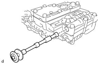
1. REMOVE MANUAL VALVE
| (a) Remove the manual valve from the transmission valve body assembly. |
|
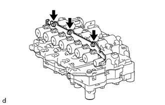
2. REMOVE SOLENOID LOCK PLATE
| (a) Remove the 3 bolts and solenoid lock plate from the transmission valve body assembly. |
|
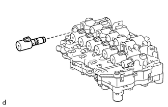
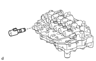
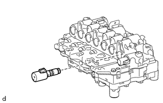
3. REMOVE SOLENOID (SLU) VALVE
| (a) Remove the solenoid (SLU) valve from the transmission valve body assembly. |
|
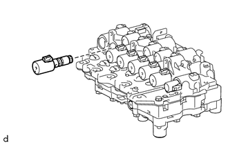
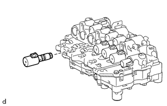
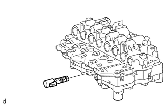
4. REMOVE SOLENOID (SL5) VALVE
| (a) Remove the solenoid (SL5) valve from the transmission valve body assembly. |
|
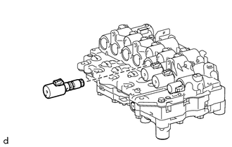
5. REMOVE SOLENOID (SL6) VALVE
| (a) Remove the solenoid (SL6) valve from the transmission valve body assembly. |
|
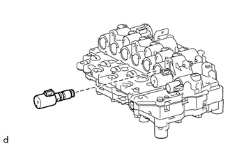
6. REMOVE SOLENOID (SL4) VALVE
| (a) Remove the solenoid (SL4) valve from the transmission valve body assembly. |
|
7. REMOVE SOLENOID (SL3) VALVE
| (a) Remove the solenoid (SL3) valve from the transmission valve body assembly. |
|
8. REMOVE SOLENOID (SL1) VALVE
| (a) Remove the solenoid (SL1) valve from the transmission valve body assembly. |
|
9. REMOVE SOLENOID (SL2) VALVE
| (a) Remove the solenoid (SL2) valve from the transmission valve body assembly. |
|
10. REMOVE SOLENOID (SLT) VALVE
| (a) Remove the solenoid (SLT) valve from the transmission valve body assembly. |
|
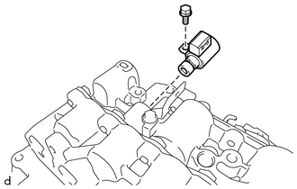
11. REMOVE SOLENOID (SL) VALVE
| (a) Remove the bolt and solenoid (SL) valve from the transmission valve body assembly. |
|
READ NEXT:
 Inspection
INSPECTION PROCEDURE 1. INSPECT SOLENOID (SL) VALVE (a) Measure the resistance according to the value(s) in the table below. Standard Resistance: Tester Connection Condition Specified Condi
Installation
INSTALLATION PROCEDURE 1. INSTALL TRANSMISSION VALVE BODY ASSEMBLY (a) Coat 2 new transaxle case gaskets with Toyota Genuine ATF WS and install them to the automatic transaxle case sub-assembly. (b) C
Reassembly
REASSEMBLY PROCEDURE 1. INSTALL SOLENOID (SL) VALVE (a) Coat the solenoid (SL) valve with Toyota Genuine ATF WS. (b) Install the solenoid (SL) valve to the transmission valve body assem
SEE MORE:
Engine Coolant Pump No Signal (P26CA31)
DESCRIPTION Refer to DTC P26CA12. Click here DTC No. Detection Item DTC Detection Condition Trouble Area MIL Memory Note P26CA31 Engine Coolant Pump No Signal The speed of the water inlet housing with water pump sub-assembly calculated from the WPI signal is less than 10 rpm
Components
COMPONENTS ILLUSTRATION *1 BATTERY SERVICE HOLE COVER *2 SERVICE PLUG GRIP ILLUSTRATION *1 CONNECTOR COVER ASSEMBLY *2 ENGINE ROOM MAIN WIRE Tightening torque for "Major areas involving basic vehicle performance such as moving/turning/stopping": N*m (kgf*cm, ft.*lbf)
