Lexus ES: Removal
REMOVAL
PROCEDURE
1. REMOVE COWL TOP VENTILATOR LOUVER SUB-ASSEMBLY
Click here .gif)
2. REMOVE FRONT CENTER UPPER SUSPENSION BRACE SUB-ASSEMBLY
Click here
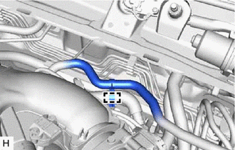
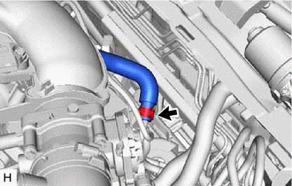
3. REMOVE UNION TO CHECK VALVE HOSE
|
(a) Disengage the clamp to separate the union to check valve hose from the air tube. |
|
|
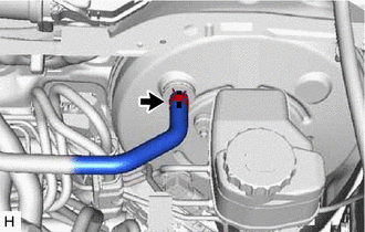
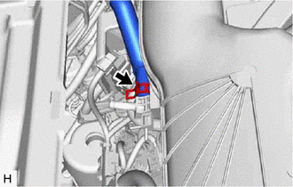
(b) Slide the clip and disconnect the union to check valve hose from the brake booster assembly. |
|
|
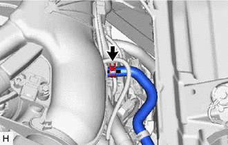
(c) Slide the clip and disconnect the union to check valve hose from the air delivery way. |
|
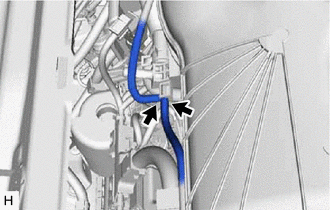
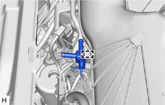
(d) Remove the 2 clips from the union to check valve hose.
4. REMOVE AIR TUBE
|
(a) Disconnect the 2 vacuum transmitting hose assemblies from the air delivery way. |
|
|
(b) Slide the clip and disconnect the air tube from the vacuum pump assembly. |
|
|
(c) Slide the clip and disconnect the air tube from the air delivery way. |
|
(d) Remove the 2 clips from the air tube.
|
(e) Disengage the clamp to remove the air delivery way from the intake air surge tank assembly. |
|
READ NEXT:
 Installation
INSTALLATION
PROCEDURE
1. INSTALL AIR TUBE
(a) Engage the clamp to install the air delivery way to the intake air
surge tank assembly.
Components
COMPONENTS
ILLUSTRATION
*1
RESERVE TANK CAP
*2
DRAIN COCK PLUG
*3
NO. 1 ENGINE UNDER COVER
-
-
SEE MORE:
Installation
INSTALLATION PROCEDURE 1. INSTALL FUEL SUCTION TUBE WITH PUMP AND GAUGE ASSEMBLY (a) Install a new fuel suction tube set gasket to the fuel tank assembly. (b) Connect the fuel return vent tube sub-assembly to the fuel suction tube with pump and gauge assembly. Click here NOTICE: When connecting th
Terminals Of Ecu
TERMINALS OF ECU CHECK AIR CONDITIONING AMPLIFIER ASSEMBLY *A w/o Seat Heater *B w/ Seat Heater (a) Disconnect the G39 air conditioning amplifier assembly connector. (b) Measure the voltage and resistance according to the value(s) in the table below. HINT: Measure the values on the wire
