Lexus ES: Installation
INSTALLATION
PROCEDURE
1. INSTALL AIR TUBE
|
(a) Engage the clamp to install the air delivery way to the intake air surge tank assembly. |
|
.png)
(b) Install the 2 clips to the air tube.
|
(c) Connect the air tube to the air delivery way and slide the clip to secure it. NOTICE:
|
|
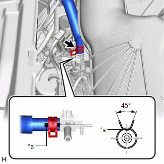
|
(d) Connect the air tube to the vacuum pump assembly and slide the clip to secure it. NOTICE:
|
|
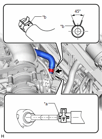
|
(e) Connect the 2 vacuum transmitting hose assemblies to the air delivery way. |
|
.png)
2. INSTALL UNION TO CHECK VALVE HOSE
(a) Install the 2 clips to the union to check valve hose.
|
(b) Connect the union to check valve hose to the air delivery way and slide the clip to secure it. NOTICE:
|
|
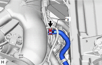
|
(c) Connect the union to check valve hose to the brake booster assembly and slide the clip to secure it. NOTICE:
|
|
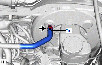
|
(d) Engage the clamp to install the union to check valve hose to the air tube. |
|
.png)
3. INSTALL FRONT CENTER UPPER SUSPENSION BRACE SUB-ASSEMBLY
Click here .gif)
4. INSTALL COWL TOP VENTILATOR LOUVER SUB-ASSEMBLY
Click here
READ NEXT:
 Components
COMPONENTS
ILLUSTRATION
*1
RESERVE TANK CAP
*2
DRAIN COCK PLUG
*3
NO. 1 ENGINE UNDER COVER
-
-
Replacement
REPLACEMENT
CAUTION / NOTICE / HINT
CAUTION:
To avoid the danger of being burned, do not remove the reserve tank cap or drain
cock plug while the coolant (for inverter) is still hot. Pressurized,
SEE MORE:
Lost Communication With Body Control Module "B" (U0142)
DESCRIPTION DTC No. Detection Item DTC Detection Condition Trouble Area U0142 Lost Communication with Main Body ECU No communication with main body ECU (multiplex network body ECU)
CAN communication system
Main body ECU (multiplex network body ECU)
PROCEDURE 1. GO
High Voltage Power Resource Internal Electronic Failure (P1C8549)
DESCRIPTION The hybrid vehicle control ECU monitors the system internal operation, it will store a DTC and perform fail-safe control if it detects the following malfunction. DTC No. Detection Item DTC Detection Condition Trouble Area MIL Warning Indicate P1C8549 High Voltage Power
