Lexus ES: Removal
REMOVAL
CAUTION / NOTICE / HINT
HINT:
- Use the same procedure for the RH side and LH side.
- The following procedure is for the LH side.
PROCEDURE
1. REMOVE REAR WHEEL
Click here .gif)
2. REMOVE REAR AXLE SHAFT NUT
| (a) Using SST and a hammer, release the staked part of the rear axle shaft nut. SST: 09930-00010 NOTICE: Loosen the staked part of the rear axle shaft nut completely, otherwise the threads of the rear drive shaft assembly may be damaged. |
|
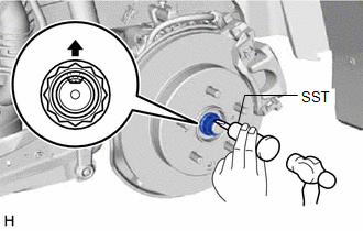
(b) While applying the brakes, using a 30 mm deep socket wrench, remove the rear axle shaft nut.
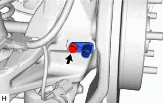
3. DISCONNECT NO. 2 PARKING BRAKE WIRE ASSEMBLY
| (a) Disconnect the No. 2 parking brake wire assembly connector from the parking brake actuator assembly. NOTICE:
|
|
.png)
| (b) Using a screwdriver with its tip wrapped with protective tape, disconnect the No. 2 parking brake wire assembly connector from the rear skid control sensor. NOTICE:
|
|

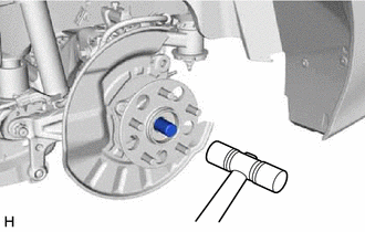
4. REMOVE REAR SKID CONTROL SENSOR
| (a) Remove the bolt and the rear skid control sensor from the rear axle carrier sub-assembly. NOTICE:
|
|
5. SEPARATE REAR DISC BRAKE CALIPER ASSEMBLY
Click here
6. REMOVE REAR DISC
Click here
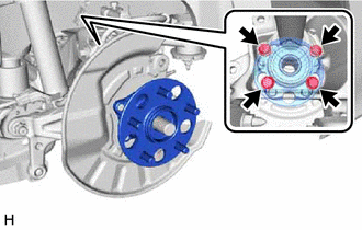
7. REMOVE REAR AXLE HUB AND BEARING ASSEMBLY
| (a) Put matchmarks on the rear drive shaft assembly and rear axle hub and bearing assembly. |
|
.png)
| (b) Using a plastic hammer, separate the rear drive shaft assembly from the rear axle hub and bearing assembly. HINT: If it is difficult to separate the rear drive shaft assembly from the rear axle hub and bearing assembly, tap the end of the rear drive shaft assembly using a brass bar and a hammer. |
|
| (c) Remove the 4 bolts, rear axle hub and bearing assembly and rear disc brake dust cover sub-assembly from the rear axle carrier sub-assembly. |
|
READ NEXT:
 Components
COMPONENTS ILLUSTRATION *1 NO. 2 PARKING BRAKE WIRE ASSEMBLY *2 REAR AXLE HUB BOLT *3 REAR DISC *4 REAR DISC BRAKE CALIPER ASSEMBLY *5 REAR FLEXIBLE HOSE - - Tight
Replacement
REPLACEMENT CAUTION / NOTICE / HINT The necessary procedures (adjustment, calibration, initialization, or registration) that must be performed after parts are removed and installed, or replaced during
SEE MORE:
Components
COMPONENTS
ILLUSTRATION
*A
w/ Battery Insulator
-
-
*1
BATTERY
*2
NEGATIVE BATTERY TERMINAL
*3
POSITIVE BATTERY TERMINAL
*4
NO. 2 BATTERY CLAMP
How To Proceed With Troubleshooting
CAUTION / NOTICE / HINT HINT:
Use the following procedure to troubleshoot the sliding roof system.
*: Use the Techstream.
PROCEDURE 1. VEHICLE BROUGHT TO WORKSHOP
NEXT 2. CUSTOMER PROBLEM ANALYSIS HINT:
In troubleshooting, confirm that the problem sympto
