Lexus ES: Installation
INSTALLATION
CAUTION / NOTICE / HINT
HINT:
- Use the same procedure for the RH side and LH side.
- The following procedure is for the LH side.
PROCEDURE
1. TEMPORARILY INSTALL REAR AXLE CARRIER SUB-ASSEMBLY
| (a) Temporarily install the rear axle carrier sub-assembly to the rear shock absorber assembly with the nut and plate washer. NOTICE: Hold the rear axle carrier pin while rotating the nut. |
|
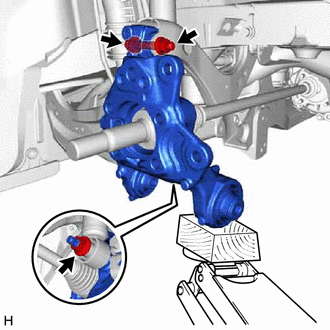
(b) Temporarily install the rear axle carrier sub-assembly to the rear upper control arm assembly with the bolt and nut.
NOTICE:
- Insert the bolt with the threaded end facing the rear of the vehicle.
- Because the nut has its own stopper, do not turn the nut. Tighten the bolt with the nut secured.
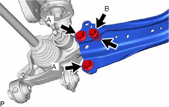
| (c) Install the rear trailing arm assembly to the rear axle carrier sub-assembly with the 3 bolts and nut. Torque: Bolt A : 135 N·m {1377 kgf·cm, 100 ft·lbf} Bolt B : 75 N·m {765 kgf·cm, 55 ft·lbf} |
|
2. INSTALL REAR FLEXIBLE HOSE BRACKET
(a) Install the rear flexible hose bracket to the rear axle carrier sub-assembly with the bolt.
Torque:
29 N·m {296 kgf·cm, 21 ft·lbf}
3. TEMPORARILY INSTALL REAR NO. 1 SUSPENSION ARM ASSEMBLY
Click here .gif)
4. INSTALL REAR LOWER COIL SPRING INSULATOR
Click here
5. INSTALL REAR COIL SPRING
Click here
6. STABILIZE SUSPENSION
Click here
7. INSTALL REAR UPPER CONTROL ARM ASSEMBLY
(a) Install the rear upper control arm assembly to the rear axle carrier sub-assembly with the bolt.
Torque:
73 N·m {744 kgf·cm, 54 ft·lbf}
NOTICE:
Because the nut has its own stopper, do not turn the nut. Tighten the bolt with the nut secured.
8. INSTALL REAR NO. 1 SUSPENSION ARM ASSEMBLY
Click here
9. INSTALL REAR NO. 2 SUSPENSION ARM ASSEMBLY
(a) Install the rear No. 2 suspension arm assembly (rear axle carrier sub-assembly side) with the bolt.
Click here
10. INSTALL REAR SHOCK ABSORBER ASSEMBLY
Click here
11. INSTALL REAR STABILIZER LINK ASSEMBLY
Click here
12. INSTALL REAR AXLE HUB AND BEARING ASSEMBLY
Click here
13. INSTALL REAR DISC
Click here
14. INSTALL REAR DISC BRAKE CALIPER ASSEMBLY
Click here
15. INSTALL REAR FLEXIBLE HOSE
(a) Install the rear flexible hose to the rear flexible hose bracket with the bolt.
Torque:
29 N·m {296 kgf·cm, 21 ft·lbf}
16. INSTALL REAR SKID CONTROL SENSOR
Click here
17. INSTALL NO. 2 PARKING BRAKE WIRE ASSEMBLY
(a) Install the No. 2 parking brake wire assembly to the rear trailing arm assembly with the nut.
Torque:
15.5 N·m {158 kgf·cm, 11 ft·lbf}
(b) Engage the 2 clamps.
(c) Connect the No. 2 parking brake wire assembly connector to the parking brake actuator assembly.
(d) Connect the No. 2 parking brake wire assembly connector to the rear skid control sensor.
18. INSTALL REAR AXLE SHAFT NUT
(a) Clean the threaded parts on the rear drive shaft assembly and a new rear axle shaft nut using non-residue solvent.
NOTICE:
- Be sure to perform this work even when using a new rear drive shaft assembly.
- Keep the threaded parts free of oil and foreign matter.
(b) Using a 30 mm deep socket wrench, temporarily install the rear axle shaft nut.
Torque:
216 N·m {2203 kgf·cm, 159 ft·lbf}
HINT:
Keep depressing the brake pedal to prevent the rear drive shaft assembly from rotating.
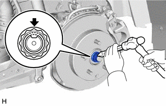
| (c) Using a chisel and hammer, stake the rear axle shaft nut. |
|
19. INSTALL REAR HEIGHT CONTROL SENSOR SUB-ASSEMBLY LH (w/ Height Control Sensor)
(a) for LH Side:
Click here
20. INSTALL REAR WHEEL
Click here
21. INSTALL REAR NO. 2 SUSPENSION ARM ASSEMBLY
(a) Install the rear No. 2 suspension arm assembly (rear suspension member sub-assembly side) with the nut.
Click here
22. INSPECT AND ADJUST REAR WHEEL ALIGNMENT
Click here
23. CHECK FOR SPEED SENSOR SIGNAL
Click here
24. PERFORM INITIALIZATION
| *1: for LED type turn signal light | |
| |
| Parking Assist Monitor System | |
| Panoramic View Monitor System | |
| Lighting System*1 | |
READ NEXT:
 Removal
REMOVAL CAUTION / NOTICE / HINT The necessary procedures (adjustment, calibration, initialization, or registration) that must be performed after parts are removed and installed, or replaced during rea
Components
COMPONENTS ILLUSTRATION *1 NO. 2 PARKING BRAKE WIRE ASSEMBLY *2 REAR AXLE HUB AND BEARING ASSEMBLY *3 REAR DISC *4 REAR DISC BRAKE CALIPER ASSEMBLY *5 REAR FLEXIBLE HOSE *6
SEE MORE:
Disassembly
DISASSEMBLY CAUTION / NOTICE / HINT HINT:
Use the same procedure for the RH side and LH side.
The following procedure is for the LH side.
PROCEDURE 1. REMOVE OUTER MIRROR Click here 2. REMOVE OUTER MIRROR COVER ASSEMBLY Click here 3. REMOVE SIDE TELEVISION CAMERA ASSEMBLY (w/ Panoramic
(Extreme) Hybrid/EV Battery Stack 1 Cell Circuit Voltage Below Threshold (P33EC16,P33ED16)
DESCRIPTION If the voltage of an HV battery cell is lower than the threshold for a certain amount of time, the battery ECU assembly will interpret this as a malfunction. DTC No. Detection Item DTC Detection Condition Trouble Area MIL Warning Indicate P33EC16 (Extreme) Hybrid/EV Ba
