Lexus ES: Components
COMPONENTS
ILLUSTRATION
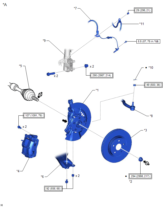
| *A | w/o AVS | - | - |
| *1 | FRONT AXLE ASSEMBLY | *2 | FRONT AXLE SHAFT NUT |
| *3 | FRONT DISC | *4 | FRONT DISC BRAKE CALIPER ASSEMBLY |
| *5 | FRONT DRIVE SHAFT ASSEMBLY | *6 | FRONT LOWER NO. 1 SUSPENSION ARM SUB-ASSEMBLY |
| *7 | FRONT SPEED SENSOR | *8 | TIE ROD ASSEMBLY |
| *9 | FRONT SHOCK ABSORBER ASSEMBLY | *10 | COTTER PIN |
| *11 | FRONT FLEXIBLE HOSE | - | - |
.png) | Tightening torque for "Major areas involving basic vehicle performance such as moving/turning/stopping": N*m (kgf*cm, ft.*lbf) | .png) | N*m (kgf*cm, ft.*lbf): Specified torque |
| ● | Non-reusable part | .png) | Toyota Body Grease W |
 | Do not apply lubricants to the threaded parts | - | - |
ILLUSTRATION
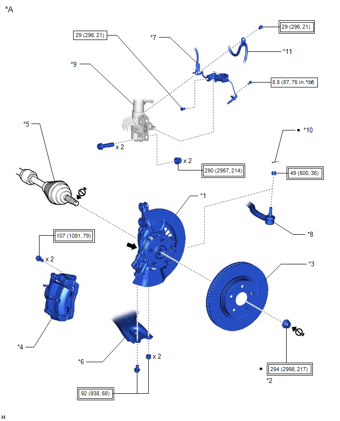
| *A | w/ AVS | - | - |
| *1 | FRONT AXLE ASSEMBLY | *2 | FRONT AXLE SHAFT NUT |
| *3 | FRONT DISC | *4 | FRONT DISC BRAKE CALIPER ASSEMBLY |
| *5 | FRONT DRIVE SHAFT ASSEMBLY | *6 | FRONT LOWER NO. 1 SUSPENSION ARM SUB-ASSEMBLY |
| *7 | FRONT SPEED SENSOR | *8 | TIE ROD ASSEMBLY |
| *9 | FRONT SHOCK ABSORBER ASSEMBLY | *10 | COTTER PIN |
| *11 | FRONT FLEXIBLE HOSE | - | - |
| | Tightening torque for "Major areas involving basic vehicle performance such as moving/turning/stopping": N*m (kgf*cm, ft.*lbf) | | N*m (kgf*cm, ft.*lbf): Specified torque |
| ● | Non-reusable part | | Toyota Body Grease W |
| | Do not apply lubricants to the threaded parts | - | - |
ILLUSTRATION
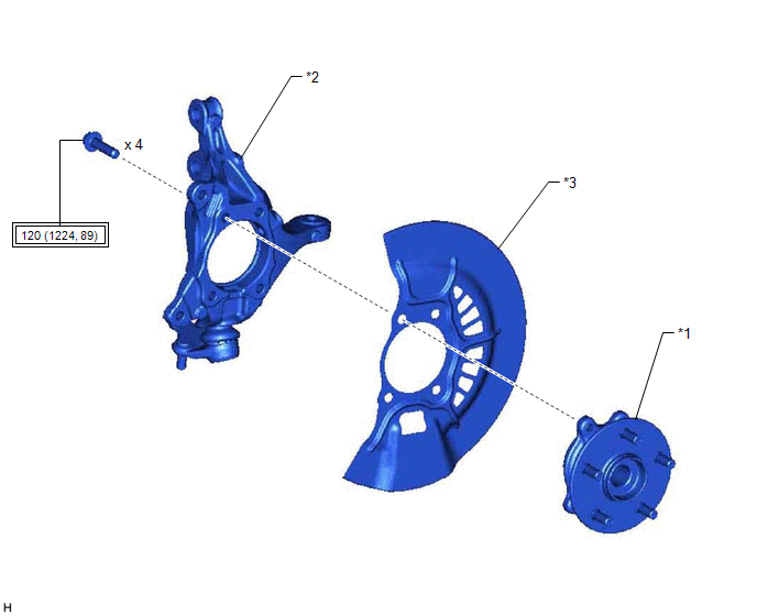
| *1 | FRONT AXLE HUB SUB-ASSEMBLY | *2 | STEERING KNUCKLE |
| *3 | FRONT DISC BRAKE DUST COVER | - | - |
| | Tightening torque for "Major areas involving basic vehicle performance such as moving/turning/stopping" : N*m (kgf*cm, ft.*lbf) | - | - |
READ NEXT:
 Installation
INSTALLATION CAUTION / NOTICE / HINT for HV Model:
When removing or installing the front disc brake caliper assembly, pushing back the disc brake piston may cause a large clearance between the brak
On-vehicle Inspection
ON-VEHICLE INSPECTION CAUTION / NOTICE / HINT The necessary procedures (adjustment, calibration, initialization, or registration) that must be performed after parts are removed and installed, or repla
Removal
REMOVAL CAUTION / NOTICE / HINT The necessary procedures (adjustment, calibration, initialization, or registration) that must be performed after parts are removed and installed, or replaced during fro
SEE MORE:
System Diagram
SYSTEM DIAGRAM Communication Table Transmitting ECU Receiving ECU Signal Communication Method Multiplex Network Master Switch Assembly Power Window Regulator Motor Assembly (for Driver Door) Power window auto up and down signal LIN
Power Window Regulator Motor Assembly (
Pressure Control Solenoid "B" Circuit Short to Battery (P077512)
DESCRIPTION Changing gears is performed by the ECM turning the solenoid (SL1, SL2, SL3, SL4, SL5 and SL6) valves on and off. If an open or short occurs in any of the solenoid valve circuits, the ECM controls the remaining normal solenoid valves to allow the vehicle to be driven. If all of the soleno
