Lexus ES: Removal
REMOVAL
CAUTION / NOTICE / HINT
The necessary procedures (adjustment, calibration, initialization, or registration) that must be performed after parts are removed and installed, or replaced during front axle hub sub-assembly removal/installation are shown below.
Necessary Procedures After Parts Removed/Installed/Replaced (for HV Model:)| Replaced Part or Performed Procedure | Necessary Procedure | Effect/Inoperative Function when Necessary Procedure not Performed | Link |
|---|---|---|---|
|
*: When performing learning using the Techstream.
Click here | |||
| Auxiliary battery terminal is disconnected/reconnected | Perform steering sensor zero point calibration | Lane Control System | |
| Pre-collision System | |||
| Parking Support Brake System* | |||
| Lighting System | |||
| Memorize steering angle neutral point | Parking Assist Monitor System | | |
| Panoramic View Monitor System | | ||
| Initialize power trunk lid system | Power Trunk Lid System (for HV Model) | | |
| Front wheel alignment adjustment |
|
| |
NOTICE:
for HV Model:- After the power switch is turned off, the radio receiver assembly records various types of memory and settings. As a result, after turning the power switch off, make sure to wait at least 85 seconds before disconnecting the cable from the negative (-) auxiliary battery terminal. (for Audio and Visual System)
- After the power switch is turned off, the radio receiver assembly records various types of memory and settings. As a result, after turning the power switch off, make sure to wait at least 85 seconds before disconnecting the cable from the negative (-) auxiliary battery terminal. (for Navigation System)
CAUTION / NOTICE / HINT
Necessary Procedures After Parts Removed/Installed/Replaced (for Gasoline Model:)| Replaced Part or Performed Procedure | Necessary Procedure | Effect/Inoperative Function when Necessary Procedure not Performed | Link |
|---|---|---|---|
| Front wheel alignment adjustment |
|
| |
- When removing or installing the front disc brake caliper assembly, pushing back the disc brake piston may cause a large clearance between the brake pads and brake disc. When the brake pedal is depressed with a large clearance between the brake pads and the brake disc, DTC C1214 related to abnormal brake fluid pressure may be stored. Make sure to clear any DTCs after performing this procedure.
- While the auxiliary battery is connected, even if the power switch is off, the brake control system activates when the brake pedal is depressed or any door courtesy switch turns on. Therefore, when servicing the brake system components, do not operate the brake pedal or open/close the doors while the auxiliary battery is connected.
HINT:
- Use the same procedure for the RH side and LH side.
- The following procedure is for the LH side.
PROCEDURE
1. PRECAUTION (for HV Model)
NOTICE:
After turning the power switch off, waiting time may be required before disconnecting the cable from the negative (-) auxiliary battery terminal. Therefore, make sure to read the disconnecting the cable from the negative (-) auxiliary battery terminal notices before proceeding with work.
2. DISABLE BRAKE CONTROL (for HV Model)
Click here .gif)
3. REMOVE FRONT WHEEL
Click here
4. REMOVE FRONT AXLE SHAFT NUT
for A25A-FXS: Click here
for 2GR-FKS: Click here
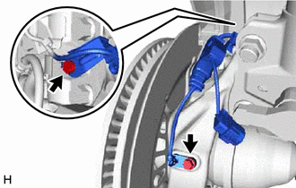
5. SEPARATE FRONT SPEED SENSOR (w/o AVS)
| (a) Remove the bolt and separate the front speed sensor and front flexible hose from the front shock absorber assembly. NOTICE: Be sure to separate the front speed sensor and front flexible hose from the front shock absorber assembly completely. |
|
.png)
| (b) Remove the bolt, disengage the clamp and separate the front speed sensor from the front shock absorber assembly and steering knuckle. NOTICE:
|
|
.png)
6. SEPARATE FRONT SPEED SENSOR (w/ AVS)
| (a) Remove the bolt and separate the front speed sensor and front flexible hose from the front shock absorber assembly. NOTICE: Be sure to separate the front speed sensor and front flexible hose from the front shock absorber assembly completely. |
|
.png)
| (b) Disconnect the AVS connector from the absorber control actuator. |
|
.png)
| (c) Remove the 2 bolts and separate the front speed sensor from the front shock absorber assembly and steering knuckle. NOTICE:
|
|
7. SEPARATE TIE ROD ASSEMBLY
Click here
8. SEPARATE FRONT DISC BRAKE CALIPER ASSEMBLY
Click here
9. REMOVE FRONT DISC
Click here
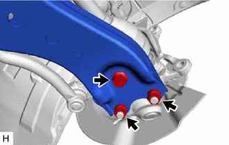
10. SEPARATE FRONT LOWER NO. 1 SUSPENSION ARM SUB-ASSEMBLY
| (a) Remove the bolt and 2 nuts and separate the front lower No. 1 suspension arm sub-assembly from the front lower ball joint assembly. |
|
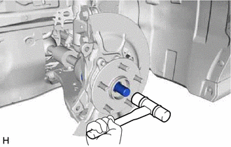
11. SEPARATE FRONT DRIVE SHAFT ASSEMBLY
| (a) Put matchmarks on the front drive shaft assembly and the front axle hub sub-assembly. |
|
.png)
| (b) Using a plastic hammer, separate the front drive shaft assembly from the front axle assembly. NOTICE:
HINT: If it is difficult to separate the front drive shaft assembly from the front axle assembly, tap the end of the front drive shaft assembly using a brass bar and a hammer. |
|
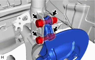
12. REMOVE FRONT AXLE ASSEMBLY
| (a) Remove the 2 bolts, 2 nuts and front axle assembly from the front shock absorber assembly. NOTICE: When removing the nuts, keep the bolts from rotating. |
|
13. REMOVE FRONT AXLE HUB SUB-ASSEMBLY
| (a) Secure the front axle assembly between aluminum plates in a vise. NOTICE: Do not overtighten the vise. |
|
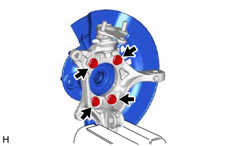
(b) Remove the 4 bolts, front axle hub sub-assembly and front disc brake dust cover from the steering knuckle.
NOTICE:
- Do not drop the front axle hub sub-assembly.
- Be careful not to damage the speed sensor rotor or contact surfaces.
- Do not allow foreign matter to contact the speed sensor rotor or contact surfaces.
READ NEXT:
 Components
COMPONENTS ILLUSTRATION *A for Gasoline Model *B for RH Side *C for LH Side - - *1 NO. 1 FLOOR UNDER COVER *2 NO. 2 FLOOR UNDER COVER N*m (kgf*cm, ft.*lbf): Specif
Installation
INSTALLATION CAUTION / NOTICE / HINT for HV Model:
When removing or installing the rear disc brake caliper assembly, pushing back the disc brake piston may cause a large clearance between the brake
SEE MORE:
Diagnostic Trouble Code Chart
DIAGNOSTIC TROUBLE CODE CHART Audio and Visual System DTC No. Detection Item Link B1323 Lost Communication with Haptic Device B1324 Lost Communication with Meter B1326 Lost Communication with Clock Device (Local-CAN) B1551 HD Radio Tuner Malfunction
Reassembly
REASSEMBLY PROCEDURE 1. INSTALL FUEL PUMP WITH FILTER ASSEMBLY HINT: Perform "Inspection After Repair" after replacing the fuel pump with filter assembly. Click here (a) Apply gasoline to a new O-ring. Then install the O-ring and fuel pump spacer to the fuel pump. *1 O-ring
