Lexus ES: Reassembly
REASSEMBLY
PROCEDURE
1. INSTALL FUEL PUMP WITH FILTER ASSEMBLY
HINT:
Perform "Inspection After Repair" after replacing the fuel pump with filter assembly.
Click here .gif)
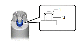
| (a) Apply gasoline to a new O-ring. Then install the O-ring and fuel pump spacer to the fuel pump. |
|
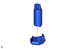
| (b) Install the fuel pump to the suction filter. |
|
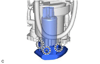
| (c) Engage the 3 claws to install the fuel pump with filter assembly to the fuel filter. NOTICE:
|
|
| (d) Connect the fuel pump harness connector to install the fuel pump harness to the fuel pump. |
|
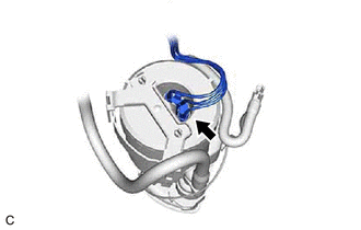
| (e) Engage the claw to connect the fuel pump harness to the fuel pump with filter assembly. NOTICE:
|
|
(f) Check the connection state of the fuel pump harness.
(1) Measure the resistance according to the value(s) in the table below.
Standard Resistance:
| Tester Connection | Condition | Specified Condition |
|---|---|---|
| Fuel pump body - Ground terminal of the fuel pump harness | Always | Below 1 Ω |
If the result is not as specified, reconnect the fuel pump harness to the fuel pump with filter assembly so that the ground terminal of the fuel pump harness is securely connected to the fuel pump body.
(g) Engage the 2 claws to install the fuel filter to the fuel sub-tank.
NOTICE:
- Do not apply excessive force to the tube or No. 1 fuel suction support.
- Securely engage the claws.
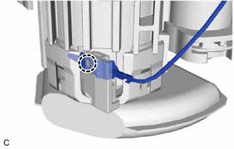
| (h) Engage the clamp and claw, and connect the fuel pump filter hose while aligning it with the installation position of the fuel sub-tank. NOTICE: Securely engage the clamp and claw. |
|
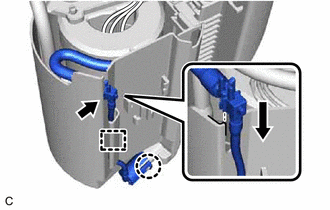
(i) Engage the clamp to connect the fuel pump harness to the fuel suction plate sub-assembly.
(j) Connect the 2 fuel pump harness connectors.
(k) Install the harness protector to the fuel pump harness.
2. INSTALL FUEL SENDER GAUGE ASSEMBLY
Click here
READ NEXT:
 Installation
INSTALLATION PROCEDURE 1. INSTALL FUEL SUCTION TUBE WITH PUMP AND GAUGE ASSEMBLY (a) Install a new fuel suction tube set gasket to the fuel tank assembly. (b) Set the fuel suction tube with pump and g
Components
COMPONENTS ILLUSTRATION *1 FUEL PUMP ASSEMBLY *2 FUEL PUMP PROTECTOR *3 NO. 1 FUEL PIPE SUB-ASSEMBLY *4 NO. 2 FUEL TUBE SUB-ASSEMBLY *5 FUEL PUMP LIFTER ASSEMBLY *6 FUEL
SEE MORE:
Adjustment
ADJUSTMENT CAUTION / NOTICE / HINT HINT:
Use the same procedure for the RH side and LH side.
The following procedure is for the LH side.
PROCEDURE 1. PREPARE VEHICLE FOR HEADLIGHT AIM ADJUSTMENT (a) Prepare the vehicle:
Ensure that there is no damage or deformation to the vehicle body aro
Diagnostic Trouble Code Chart
DIAGNOSTIC TROUBLE CODE CHART Telematics System DTC No. Detection Item Link U014087 Lost Communication with Body Control Module Missing Message U015587 Lost Communication with Instrument Panel Cluster (IPC) Control Module Missing Message U016387 Lost Communication
