Lexus ES: Components
COMPONENTS
ILLUSTRATION
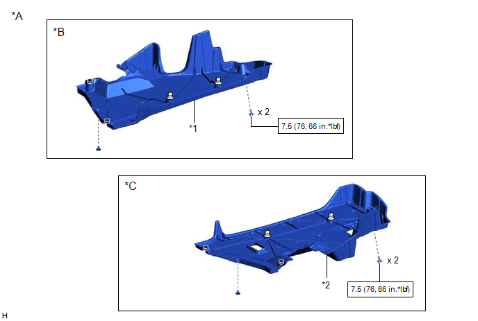
| *A | for Gasoline Model | *B | for RH Side |
| *C | for LH Side | - | - |
| *1 | NO. 1 FLOOR UNDER COVER | *2 | NO. 2 FLOOR UNDER COVER |
.png) | N*m (kgf*cm, ft.*lbf): Specified torque | - | - |
ILLUSTRATION
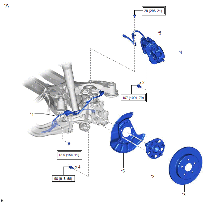
| *A | w/o AVS | - | - |
| *1 | NO. 2 PARKING BRAKE WIRE ASSEMBLY | *2 | REAR AXLE HUB AND BEARING ASSEMBLY |
| *3 | REAR DISC | *4 | REAR DISC BRAKE CALIPER ASSEMBLY |
| *5 | REAR FLEXIBLE HOSE | *6 | REAR DISC BRAKE DUST COVER SUB-ASSEMBLY |
.png) | Tightening torque for "Major areas involving basic vehicle performance such as moving/turning/stopping": N*m (kgf*cm, ft.*lbf) | - | - |
ILLUSTRATION
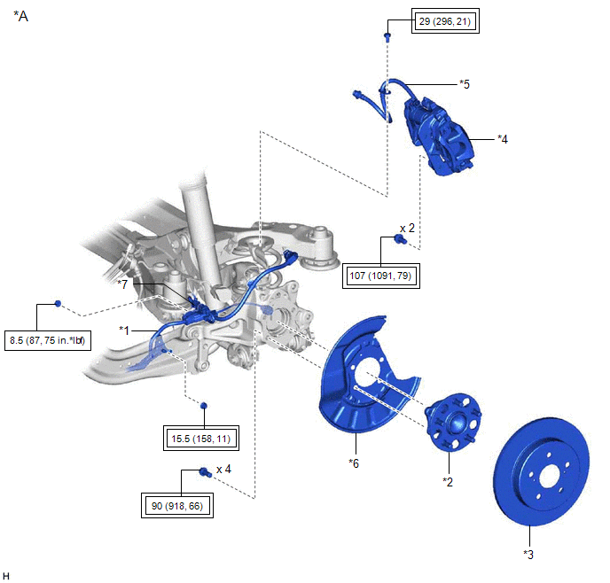
| *A | w/ AVS | - | - |
| *1 | NO. 2 PARKING BRAKE WIRE ASSEMBLY | *2 | REAR AXLE HUB AND BEARING ASSEMBLY |
| *3 | REAR DISC | *4 | REAR DISC BRAKE CALIPER ASSEMBLY |
| *5 | REAR FLEXIBLE HOSE | *6 | REAR DISC BRAKE DUST COVER SUB-ASSEMBLY |
| *7 | WIRE HARNESS BRACKET | - | - |
| | Tightening torque for "Major areas involving basic vehicle performance such as moving/turning/stopping": N*m (kgf*cm, ft.*lbf) | | N*m (kgf*cm, ft.*lbf): Specified torque |
ILLUSTRATION
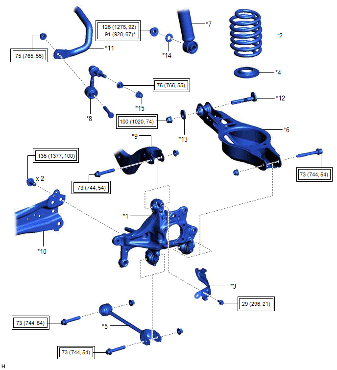
| *1 | REAR AXLE CARRIER SUB-ASSEMBLY | *2 | REAR COIL SPRING |
| *3 | REAR FLEXIBLE HOSE BRACKET | *4 | REAR LOWER COIL SPRING INSULATOR |
| *5 | REAR NO. 1 SUSPENSION ARM ASSEMBLY | *6 | REAR NO. 2 SUSPENSION ARM ASSEMBLY |
| *7 | REAR SHOCK ABSORBER ASSEMBLY | *8 | REAR STABILIZER LINK ASSEMBLY |
| *9 | REAR UPPER CONTROL ARM ASSEMBLY | *10 | REAR TRAILING ARM ASSEMBLY |
| *11 | REAR STABILIZER BAR | *12 | REAR SUSPENSION TOE ADJUST CAM SUB-ASSEMBLY |
| *13 | NO. 2 CAMBER ADJUST CAM | *14 | PLATE WASHER |
| *15 | CAP | - | - |
| | Tightening torque for "Major areas involving basic vehicle performance such as moving/turning/stopping": N*m (kgf*cm, ft.*lbf) | * | For use with a ball joint lock nut wrench |
READ NEXT:
 Installation
INSTALLATION CAUTION / NOTICE / HINT for HV Model:
When removing or installing the rear disc brake caliper assembly, pushing back the disc brake piston may cause a large clearance between the brake
Removal
REMOVAL CAUTION / NOTICE / HINT The necessary procedures (adjustment, calibration, initialization, or registration) that must be performed after parts are removed and installed, or replaced during rea
SEE MORE:
Data List / Active Test
DATA LIST / ACTIVE TEST ACTIVE TEST HINT: Using the Techstream to perform Active Tests allows relays, VSVs, actuators and other items to be operated without removing any parts. This non-intrusive functional inspection can be very useful because intermittent operation may be discovered before parts o
Data List / Active Test
DATA LIST / ACTIVE TEST DATA LIST NOTICE:
Some Data List values may vary significantly if there are slight differences in the environment in which the vehicle is operating when measurements are obtained. Variations may also occur due to aging of the vehicle. Due to these considerations, it is not
