Lexus ES: System Diagram
Lexus ES (XZ10) Service Manual / Engine & Hybrid System / 2gr-fks (emission Control) / Emission Control System / System Diagram
SYSTEM DIAGRAM
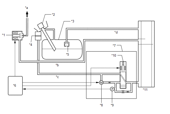
| *1 | Purge Valve (Purge VSV) | *2 | Fuel Tank Cap Assembly |
| *3 | Fuel Tank Assembly | *4 | Canister Filter |
| *5 | Fuel Cut-off Valve | *6 | ECM |
| *7 | Canister Pump Module (Leak Detection Pump Sub-assembly) | *8 | Pump Motor |
| *9 | Canister Pressure Sensor | *10 | Vent Valve |
| *11 | Canister (Charcoal Canister Assembly) | - | - |
| *a | to Intake Manifold | *b | Purge Line |
| *c | Air Line | *d | Vent Line |
READ NEXT:
 On-vehicle Inspection
ON-VEHICLE INSPECTION CAUTION / NOTICE / HINT CAUTION: To prevent injury due to contact with an operating V-ribbed belt or cooling fan, keep your hands and clothing away from the V-ribbed belt and coo
Fuel Tank Cap
InspectionINSPECTION PROCEDURE 1. INSPECT FUEL TANK CAP ASSEMBLY (a) Visually check that the fuel tank cap assembly and gasket are not deformed or damaged. If the result is not as specified, repla
Pcv Valve
ComponentsCOMPONENTS ILLUSTRATION *1 PCV VALVE (VENTILATION VALVE SUB-ASSEMBLY) *2 V-BANK COVER SUB-ASSEMBLY *3 VENTILATION HOSE - - N*m (kgf*cm, ft.*lbf): Specified torque
SEE MORE:
Voice is not Recognized
PROCEDURE 1. CHECK CONDITION (a) While paying attention to the condition of the spoken voice command, perform a voice recognition operation. OK: Voice command is recognized normally. HINT:
When the voice command is recognized, the content of the voice command is displayed in the voice r
Rear Brake Flexible Hose
ComponentsCOMPONENTS ILLUSTRATION *1 REAR FLEXIBLE HOSE *2 GASKET *3 UNION BOLT *4 BRAKE LINE Tightening torque for "Major areas involving basic vehicle performance such as moving/turning/stopping": N*m (kgf*cm, ft.*lbf) * For use with a union nut wrench ● Non
© 2016-2026 Copyright www.lexguide.net
