Lexus ES: Removal
REMOVAL
CAUTION / NOTICE / HINT
HINT:
- Use the same procedure for the RH side and LH side.
- The following procedure is for the LH side.
- The front speed sensor rotor is a component of the front axle hub sub-assembly. If the front speed sensor rotor is malfunctioning, replace the front axle hub sub-assembly.
PROCEDURE
1. REMOVE FRONT WHEEL
Click here .gif)
2. REMOVE FRONT WHEEL OPENING EXTENSION PAD (w/o AVS)
for A25A-FXS: Click here
for 2GR-FKS: Click here
3. SEPARATE FRONT FENDER LINER (w/o AVS)
| (a) Remove the screw and 5 clips. |
|
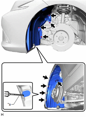
(b) Using a screwdriver with its tip wrapped with protective tape, disengage the 3 claws to separate the front fender liner.
4. REMOVE FRONT SPEED SENSOR (w/o AVS)
(a) Turn back the front fender liner.
| (b) Disconnect the front speed sensor connector. |
|
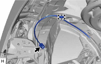
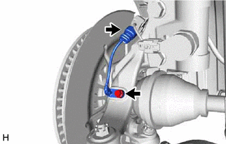
(c) Disengage the clamp.
| (d) Remove the bolt and separate the sensor clamp. |
|
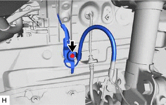
| (e) Remove the bolt and separate the front flexible hose and sensor clamp. |
|
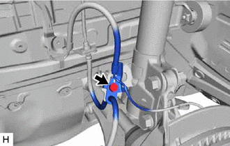
| (f) Disengage the clamp to separate the sensor clamp. |
|
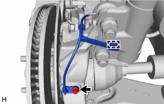
(g) Remove the bolt and front speed sensor from the steering knuckle.
NOTICE:
- Keep the tip of the front speed sensor and installation hole free of foreign matter.
- Do not rotate or apply excessive force to the front speed sensor when removing it from the steering knuckle. Rotating or applying excessive force may result in damage to the front speed sensor.
5. REMOVE FRONT SPEED SENSOR (w/ AVS)
| (a) Disconnect the front speed sensor connector. |
|
(b) Remove the bolt and front speed sensor from the steering knuckle.
NOTICE:
- Keep the tip of the front speed sensor and installation hole free of foreign matter.
- Do not rotate or apply excessive force to the front speed sensor when removing it from the steering knuckle. Rotating or applying excessive force may result in damage to the front speed sensor.
READ NEXT:
 Removal
REMOVAL CAUTION / NOTICE / HINT HINT:
Use the same procedure for the RH side and LH side.
The following procedure is for the LH side.
The front speed sensor rotor is a component of the front ax
Rear Speed Sensor (for Awd)
ComponentsCOMPONENTS ILLUSTRATION *1 REAR SKID CONTROL SENSOR *2 NO. 2 PARKING BRAKE WIRE ASSEMBLY Tightening torque for "Major areas involving basic vehicle performance such as movi
SEE MORE:
Installation
INSTALLATION PROCEDURE 1. TEMPORARILY INSTALL FUEL PUMP ASSEMBLY (a) Turn the crankshaft pulley until the flat of the camshaft faces the fuel pump lifter assembly. HINT: This prevents the camshaft nose from pushing up the fuel pump lifter assembly when installing the fuel pump assembly.
Brake Switch "A" Circuit Open (P057113)
DESCRIPTION The skid control ECU (brake actuator assembly) receives stop light switch assembly signals and uses them to determine whether or not the brakes are applied. The skid control ECU (brake actuator assembly) has a detection circuit that it uses to detect an open in the stop light input line.
