Lexus ES: 2gr-fks Drive Belt
Components
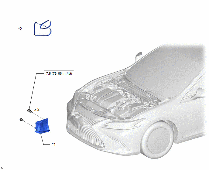
COMPONENTS
ILLUSTRATION
|
*1 |
FRONT FENDER APRON SEAL RH |
*2 |
V-RIBBED BELT |
.png) |
N*m (kgf*cm, ft.*lbf): Specified torque |
- |
- |
Removal
REMOVAL
PROCEDURE
1. REMOVE FRONT WHEEL RH
Click here .gif)
2. REMOVE FRONT FENDER APRON SEAL RH
Click here
3. REMOVE V-RIBBED BELT
|
(a) Release the V-ribbed belt tension by turning the V-ribbed belt tensioner assembly counterclockwise. |
|
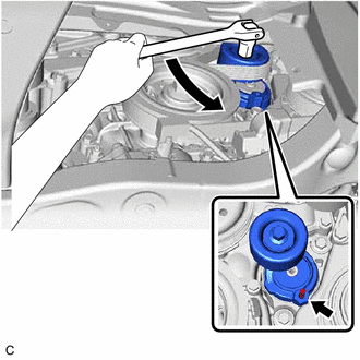
(b) Turn the V-ribbed belt tensioner assembly counterclockwise to align its holes, and then insert a 5 mm hexagon wrench to secure the V-ribbed belt tensioner assembly.
(c) Remove the V-ribbed belt from the V-ribbed belt tensioner assembly.
Installation
INSTALLATION
PROCEDURE
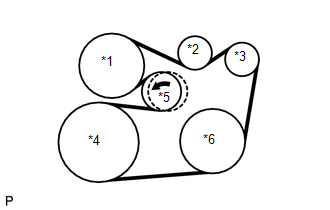
1. INSTALL V-RIBBED BELT
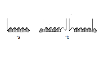
HINT:
When reusing the V-ribbed belt, check the ribs and back of the V-ribbed belt for wear and cracks. If wear or a crack that reaches the core (at more than 1 point) is found, replace the V-ribbed belt.
|
(a) Install the V-ribbed belt. NOTICE:
|
|
(b) Turn the V-ribbed belt tensioner assembly counterclockwise and remove the 5 mm hexagon wrench.
|
(c) After installing the V-ribbed belt, check that it fits properly in the ribbed grooves. Confirm that the V-ribbed belt has not slipped out of the grooves on the bottom of the pulley by hand. |
|
2. INSTALL FRONT FENDER APRON SEAL RH
Click here .gif)
3. INSTALL FRONT WHEEL RH
Click here
READ NEXT:
 Components
COMPONENTS
ILLUSTRATION
*A
Type A
*B
Type B
*1
FRONT WHEEL OPENING EXTENSION PAD LH
*2
FRONT WHEEL OPE
Replacement
REPLACEMENT
CAUTION / NOTICE / HINT
CAUTION:
Prolonged and repeated contact with engine oil will result in the removal
of natural oils from the skin, leading to dryness, irritation and
SEE MORE:
Position Initialization Incomplete (B2343)
DESCRIPTION This DTC is stored when the sliding roof ECU (sliding roof drive gear sub-assembly) has not been initialized. DTC No. Detection Item DTC Detection Condition Trouble Area B2343 Position Initialization Incomplete Sliding roof ECU (sliding roof drive gear sub-assembly) has
Terminals Of Ecu
TERMINALS OF ECU CHECK SLIDING ROOF ECU (SLIDING ROOF DRIVE GEAR SUB-ASSEMBLY) (a) Disconnect the P22 sliding roof ECU (sliding roof drive gear sub-assembly) connector. (b) Measure the resistance and voltage according to the value(s) in the table below. HINT: Measure the values on the wire harness
