Lexus ES: Removal
REMOVAL
CAUTION / NOTICE / HINT
The necessary procedures (adjustment, calibration, initialization or registration) that must be performed after parts are removed and installed, or replaced during brake actuator assembly removal/installation are shown below.
Necessary Procedures After Parts Removed/Installed/Replaced| Replaced Part or Performed Procedure | Necessary Procedure | Effect/Inoperative Function when Necessary Procedure not Performed | Link |
|---|---|---|---|
|
*: When performing learning using the Techstream.
Click here | |||
| Battery terminal is disconnected/reconnected | Perform steering sensor zero point calibration | Lane Control System | |
| Pre-collision System | |||
| Parking Support Brake System* | |||
| Lighting System | |||
| Memorize steering angle neutral point | Parking Assist Monitor System | | |
| Panoramic View Monitor System | | ||
| Initialize power trunk lid system | Power Trunk Lid System | | |
| Replacement of brake actuator assembly | Perform acceleration sensor zero point calibration and store system information memorization. |
| |
| Operate the electric parking brake switch assembly | Parking brake indicator light (red) blinks when the engine switch is first turned on (IG) | | |
NOTICE:
- After the engine switch is turned off, the radio receiver assembly records various types of memory and settings. As a result, after turning the engine switch off, make sure to wait at least 85 seconds before disconnecting the cable from the negative (-) battery terminal. (for Audio and Visual System)
- After the engine switch is turned off, the radio receiver assembly records various types of memory and settings. As a result, after turning the engine switch off, make sure to wait at least 85 seconds before disconnecting the cable from the negative (-) battery terminal. (for Navigation System)
PROCEDURE
1. PRECAUTION
NOTICE:
After turning the engine switch off, waiting time may be required before disconnecting the cable from the negative (-) battery terminal. Therefore, make sure to read the disconnecting the cable from the negative (-) battery terminal notices before proceeding with work.
2. DISCONNECT CABLE FROM NEGATIVE BATTERY TERMINAL
Click here .gif)
NOTICE:
When disconnecting the cable, some systems need to be initialized after the cable is reconnected.
Click here
3. DRAIN BRAKE FLUID
NOTICE:
If brake fluid leaks onto any painted surface, immediately wash it off.
4. REMOVE FRONT WHEEL RH
Click here
5. REMOVE COWL TOP VENTILATOR LOUVER SUB-ASSEMBLY
Click here
6. REMOVE FRONT CENTER UPPER SUSPENSION BRACE SUB-ASSEMBLY
| (a) Disconnect the connector. |
|
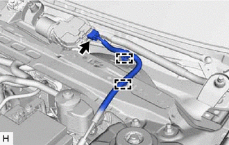
(b) Disengage the 2 clamps and separate the wire harness.
(c) w/ Windshield Deicer System:
| (1) Disconnect the connector. |
|

(2) Disengage the 3 clamps and separate the wire harness.
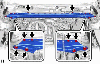
| (d) Remove the 6 bolts, 4 nuts and front center upper suspension brace sub-assembly. |
|
7. REMOVE BRAKE ACTUATOR WITH BRACKET
(a) Release the lock lever and disconnect the connector from the brake actuator assembly.
.png) | Release the lock lever |
.png) | Disconnect the connector |
NOTICE:
Be careful not to allow any brake fluid to enter the connector.
| (b) Use tags or make a memo to identify the places to reconnect the brake lines. |
|
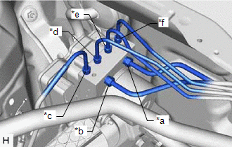
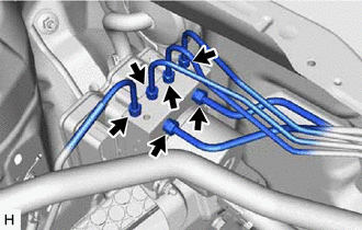
| (c) Using a union nut wrench, disconnect the 6 brake lines from the brake actuator assembly. NOTICE:
|
|
| (d) Disengage the 2 clamps to remove the No. 4 brake tube clamp from the brake lines. |
|
.png)
| (e) Using a union nut wrench, disconnect the front No. 3 brake tube while holding the front flexible hose with a wrench. NOTICE:
|
|
.png)
| (f) Disengage the clamp and separate the front No. 3 brake tube. NOTICE: Do not kink or damage the front No. 3 brake tube. |
|
.png)
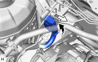
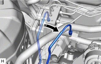
| (g) Move aside the front No. 3 brake tube as shown in the illustration. NOTICE: Do not apply excessive force to the front No. 3 brake tube. |
|
| (h) Disengage the clamp and remove the brake tube clamp. |
|
.png)
(i) Apply protective tape to the vehicle body as shown in the illustration.
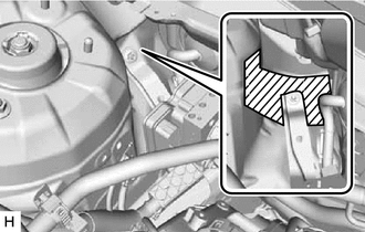
.png) | Protective Tape |
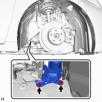
| (j) Remove the 2 bolts. HINT: Insert the tool from the bottom of the vehicle. |
|
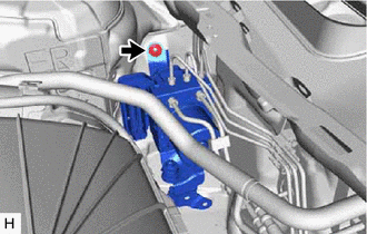
| (k) Remove the nut and brake actuator with bracket. NOTICE:
HINT: Remove the brake actuator with bracket while avoiding the brake lines. |
|
8. REMOVE BRAKE ACTUATOR ASSEMBLY
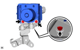
| (a) Remove the 3 bolts and brake actuator assembly from the brake actuator bracket assembly. NOTICE:
|
|
9. REMOVE NO. 2 BRAKE ACTUATOR CASE COLLAR
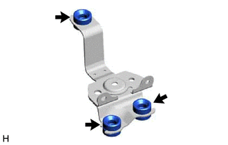
| (a) Remove the 3 nuts. |
|

(b) Remove the 3 No. 2 brake actuator case collars from the brake actuator bracket cushion.
10. REMOVE BRAKE ACTUATOR BRACKET CUSHION
| (a) Remove the 3 brake actuator bracket cushions from the brake actuator bracket assembly. |
|
READ NEXT:
 Components
COMPONENTS ILLUSTRATION *1 FRONT STABILIZER LINK ASSEMBLY RH - - Tightening torque for "Major areas involving basic vehicle performance such as moving/turning/stopping": N*m (kgf*cm,
Inspection
INSPECTION PROCEDURE 1. INSPECT BRAKE ACTUATOR ASSEMBLY (a) Inspect the solenoid circuit. (1) Make sure that there is no looseness at the locking part and the connecting part of the connector. OK: Th
SEE MORE:
Data List / Active Test
DATA LIST / ACTIVE TEST DATA LIST HINT: Using the Techstream to read the Data List allows the values or states of switches, sensors, actuators and other items to be read without removing any parts. This non-intrusive inspection can be very useful because intermittent conditions or signals may be dis
Diagnostic Trouble Code Chart
DIAGNOSTIC TROUBLE CODE CHART SFI System DTC No. Detection Item MIL Memory Note Link P001013 A Camshaft Position Actuator Bank 1 Circuit Open Comes on DTC stored SAE Code: P0010 P001100 Camshaft Position "A" - Timing Over-Advanced or System Performance Bank 1 Co
