Lexus ES: Inspection
INSPECTION
PROCEDURE
1. INSPECT BRAKE ACTUATOR ASSEMBLY
(a) Inspect the solenoid circuit.
(1) Make sure that there is no looseness at the locking part and the connecting part of the connector.
OK:
The connector is securely connected.
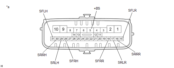
| *a | Component without harness connected (Brake Actuator Assembly) | - | - |
(2) Disconnect the brake actuator assembly connector.
(3) Check both the connector case and the terminals for deformation and corrosion.
OK:
No deformation or corrosion.
(4) Measure the resistance according to the value(s) in the table below.
HINT:
- Check the brake actuator assembly when it is cooled down.
- If the result is not as specified, replace the brake actuator assembly.
Standard Resistance:
| Tester Connection | Condition | Specified Condition |
|---|---|---|
| 5 (+BS) - 28 (SFRH) | Always | 6.4 to 7.0 Ω |
| 5 (+BS) - 31 (SFLH) | Always | 6.4 to 7.0 Ω |
| 5 (+BS) - 30 (SRRH) | Always | 6.4 to 7.0 Ω |
| 5 (+BS) - 29 (SRLH) | Always | 6.4 to 7.0 Ω |
| 5 (+BS) - 18 (SFRR) | Always | 5.1 to 5.7 Ω |
| 5 (+BS) - 15 (SFLR) | Always | 5.1 to 5.7 Ω |
| 5 (+BS) - 16 (SRRR) | Always | 5.1 to 5.7 Ω |
| 5 (+BS) - 17 (SRLR) | Always | 5.1 to 5.7 Ω |
READ NEXT:
 Installation
INSTALLATION CAUTION / NOTICE / HINT HINT: The parking brake indicator light blinks (red) when the power switch is turned on after replacing the brake actuator assembly. Operate the electric parking b
Removal
REMOVAL CAUTION / NOTICE / HINT The necessary procedures (adjustment, calibration, initialization, or registration) that must be performed after parts are removed, installed, or replaced during brake
Brake Hold Switch
ComponentsCOMPONENTS ILLUSTRATION *1 BRAKE HOLD SWITCH (NO. 2 COMBINATION SWITCH ASSEMBLY) *2 REAR UPPER CONSOLE PANEL SUB-ASSEMBLY InspectionINSPECTION PROCEDURE 1. INSPECT BRAKE HOLD
SEE MORE:
Parts Location
PARTS LOCATION ILLUSTRATION *1 MILLIMETER WAVE RADAR SENSOR ASSEMBLY *2 FORWARD RECOGNITION CAMERA *3 BRAKE BOOSTER WITH MASTER CYLINDER ASSEMBLY - SKID CONTROL ECU *4 BRAKE ACTUATOR ASSEMBLY - PARKING BRAKE ECU ILLUSTRATION *1 STOP LIGHT SWITCH ASSEMBLY *2 SPIRAL CA
Installation
INSTALLATION PROCEDURE 1. INSTALL LEAK DETECTION PUMP SUB-ASSEMBLY HINT: Only perform this procedure when replacement of the leak detection pump sub-assembly is necessary. (a) Engage the 2 claws to install a new leak detection pump sub-assembly to the No. 2 charcoal canister sub-assembly. NOTIC
