Lexus ES: Components
COMPONENTS
ILLUSTRATION
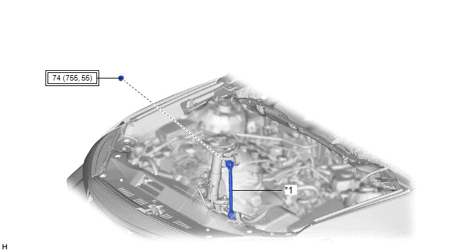
| *1 | FRONT STABILIZER LINK ASSEMBLY RH | - | - |
.png) | Tightening torque for "Major areas involving basic vehicle performance such as moving/turning/stopping": N*m (kgf*cm, ft.*lbf) | - | - |
ILLUSTRATION
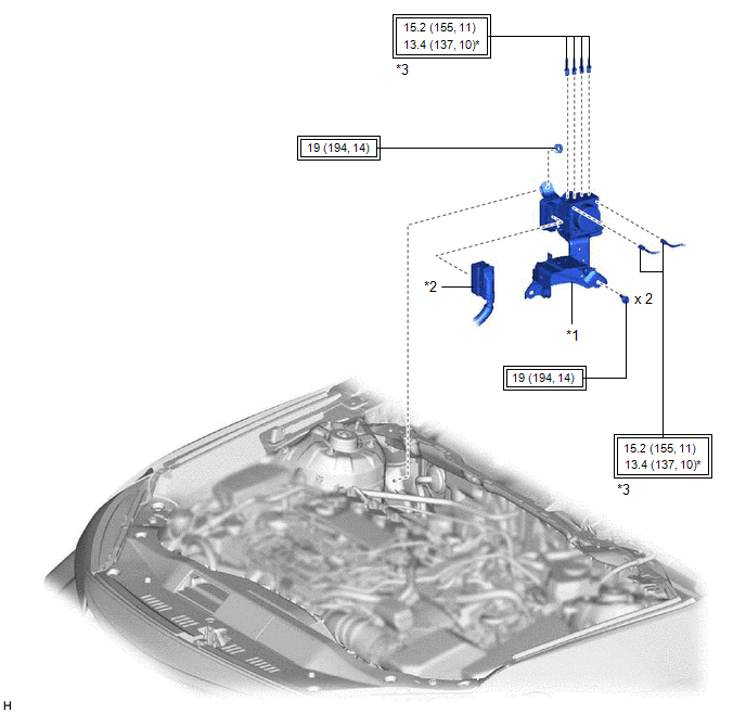
| *1 | BRAKE ACTUATOR WITH BRACKET | *2 | CONNECTOR |
| *3 | BRAKE LINE | - | - |
| | Tightening torque for "Major areas involving basic vehicle performance such as moving/turning/stopping": N*m (kgf*cm, ft.*lbf) | * | For use with a union nut wrench |
ILLUSTRATION
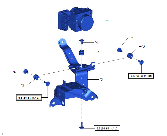
| *1 | BRAKE ACTUATOR ASSEMBLY | *2 | BRAKE ACTUATOR BOLT CUSHION |
| *3 | BRAKE ACTUATOR BRACKET ASSEMBLY | *4 | BRAKE ACTUATOR CASE COLLAR |
| | Tightening torque for "Major areas involving basic vehicle performance such as moving/turning/stopping": N*m (kgf*cm, ft.*lbf) | - | - |
READ NEXT:
 Inspection
INSPECTION PROCEDURE 1. INSPECT BRAKE ACTUATOR ASSEMBLY (a) Inspect the solenoid circuit. (1) Make sure that there is no looseness at the locking part and the connecting part of the connector. OK: Th
Installation
INSTALLATION CAUTION / NOTICE / HINT HINT: The parking brake indicator light blinks (red) when the power switch is turned on after replacing the brake actuator assembly. Operate the electric parking b
Removal
REMOVAL CAUTION / NOTICE / HINT The necessary procedures (adjustment, calibration, initialization, or registration) that must be performed after parts are removed, installed, or replaced during brake
SEE MORE:
Components
COMPONENTS ILLUSTRATION *1 FRONT FENDER APRON SEAL LH *2 FRONT FENDER APRON SEAL RH *3 FRONT WHEEL OPENING EXTENSION PAD LH *4 FRONT WHEEL OPENING EXTENSION PAD RH *5 NO. 1 ENGINE UNDER COVER *6 NO. 2 ENGINE UNDER COVER N*m (kgf*cm, ft.*lbf): Specified torque -
Diagnostic Trouble Code Chart
DIAGNOSTIC TROUBLE CODE CHART Front Camera System DTC No. Detection Item Link C10001C Control Module Internal Temperature Sensor "A" Circuit Circuit Voltage Out of Range C10051C Control Module Internal Temperature Sensor "B" Circuit Circuit Voltage Out of Range C100A
© 2016-2026 Copyright www.lexguide.net
