Lexus ES: Installation
INSTALLATION
PROCEDURE
1. INSTALL NO. 2 EXHAUST MANIFOLD HEAT INSULATOR
(a) Type A
(1) Install the No. 2 exhaust manifold heat insulator to the exhaust manifold (TWC: Front Catalyst) with the 6 bolts.
Torque:
11 N·m {112 kgf·cm, 8 ft·lbf}
(b) Type B
(1) Install the No. 2 exhaust manifold heat insulator to the exhaust manifold (TWC: Front Catalyst) with the 3 bolts.
Torque:
11 N·m {112 kgf·cm, 8 ft·lbf}
2. INSTALL EXHAUST MANIFOLD (TWC: Front Catalyst)
(a) Install a new exhaust manifold to head gasket to the cylinder head sub-assembly.
(b) Temporarily install the exhaust manifold (TWC: Front Catalyst), No. 1 upper front floor heat insulator and No. 1 exhaust manifold heat insulator.
HINT:
At this time, do not install the parts with bolts or nuts.
| (c) Temporarily install the exhaust manifold (TWC: Front Catalyst) to the cylinder head sub-assembly with 7 new nuts. |
|
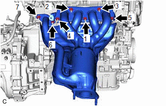
(d) Using a 12 mm deep socket wrench, tighten the 7 nuts in the order shown in the illustration.
Torque:
26 N·m {265 kgf·cm, 19 ft·lbf}
3. INSTALL MANIFOLD STAY
| (a) Temporarily install the manifold stay to the exhaust manifold (TWC: Front Catalyst) and cylinder block sub-assembly with the bolt and nut. |
|
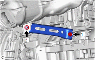
(b) Tighten the bolt and nut in the order shown in the illustration.
Torque:
43 N·m {438 kgf·cm, 32 ft·lbf}
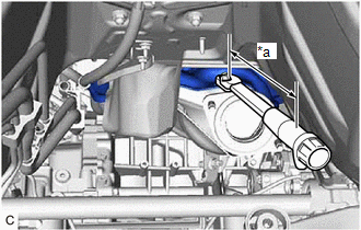
4. INSTALL NO. 1 EXHAUST MANIFOLD HEAT INSULATOR
| (a) Type A (1) Using a 10 mm union nut wrench, install the No. 1 exhaust manifold heat insulator to the exhaust manifold (TWC: Front Catalyst) with the 5 bolts. Torque: Specified tightening torque : 10 N·m {102 kgf·cm, 7 ft·lbf} HINT:
|
|
(b) Type B
(1) Install the No. 1 exhaust manifold heat insulator to the exhaust manifold (TWC: Front Catalyst) with the 3 bolts.
Torque:
10 N·m {102 kgf·cm, 7 ft·lbf}
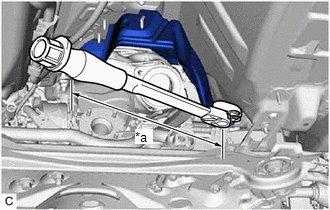
5. INSTALL NO. 1 UPPER FRONT FLOOR HEAT INSULATOR
| (a) Using a 10 mm union nut wrench, install the No. 1 upper front floor heat insulator to the vehicle body with the 3 nuts. Torque: Specified tightening torque : 4.9 N·m {50 kgf·cm, 43 in·lbf} HINT:
|
|
6. INSTALL WIRE HARNESS CLAMP BRACKET
(a) Install the wire harness clamp bracket with the bolt.
Torque:
13 N·m {133 kgf·cm, 10 ft·lbf}
7. INSTALL AIR FUEL RATIO SENSOR (for Sensor 1)
Click here .gif)
8. INSTALL FRONT CENTER UPPER SUSPENSION BRACE SUB-ASSEMBLY
Click here
9. INSTALL COWL TOP VENTILATOR LOUVER SUB-ASSEMBLY
Click here
10. INSTALL FRONT LOWER NO. 1 FLOOR HEAT INSULATOR
Click here
11. INSTALL PROPELLER WITH CENTER BEARING SHAFT ASSEMBLY
Click here
12. INSTALL FRONT EXHAUST PIPE ASSEMBLY (TWC: Rear Catalyst)
(a) Install 2 new gaskets to the front exhaust pipe assembly (TWC: Rear Catalyst).
(b) Connect the front exhaust pipe assembly (TWC: Rear Catalyst) to the 2 exhaust pipe supports.
(c) Install the front exhaust pipe assembly (TWC: Rear Catalyst) to the exhaust manifold (TWC: Front Catalyst) and center exhaust pipe assembly with 2 new bolts and 2 new nuts.
Torque:
43 N·m {438 kgf·cm, 32 ft·lbf}
(d) Connect the air fuel ratio sensor (for sensor 2) connector.
(e) Engage the 2 wire harness clamps.
13. INSTALL CENTER FLOOR CROSSMEMBER BRACE
Click here
14. INSTALL FRONT CENTER FLOOR BRACE
Click here
15. INSTALL FRONT FLOOR COVER LH
Click here
16. INSTALL FRONT FLOOR COVER RH
Click here
17. INSPECT FOR EXHAUST GAS LEAK
Click here
18. INSTALL NO. 2 ENGINE UNDER COVER ASSEMBLY
Click here
19. INSTALL NO. 1 ENGINE UNDER COVER
Click here
20. INSTALL FRONT WHEEL OPENING EXTENSION PAD LH
Click here
21. INSTALL FRONT WHEEL OPENING EXTENSION PAD RH
Click here
READ NEXT:
 Components
COMPONENTS ILLUSTRATION *1 FRONT FLOOR COVER LH *2 FRONT FLOOR COVER RH N*m (kgf*cm, ft.*lbf): Specified torque - - ILLUSTRATION *1 CENTER FLOOR CROSSMEMBER BRACE *2
Removal
REMOVAL CAUTION / NOTICE / HINT The necessary procedures (adjustment, calibration, initialization or registration) that must be performed after parts are removed and installed, or replaced during fron
SEE MORE:
Parts Location
PARTS LOCATION ILLUSTRATION *1 OUTER REAR VIEW MIRROR ASSEMBLY RH *2 OUTER REAR VIEW MIRROR ASSEMBLY LH *3 BRAKE BOOSTER WITH MASTER CYLINDER ASSEMBLY - SKID CONTROL ECU *4 HYBRID VEHICLE CONTROL ECU *5 OUTER MIRROR CONTROL ECU ASSEMBLY RH *6 OUTER MIRROR CONTROL ECU AS
Data List / Active Test
DATA LIST / ACTIVE TEST DATA LIST NOTICE: In the following table, the values listed under "Normal Condition" are reference values. Do not depend solely on these reference values when deciding whether a part is faulty or not. HINT: Using the Techstream to read the Data List allows the values or state
