Lexus ES: Components
COMPONENTS
ILLUSTRATION
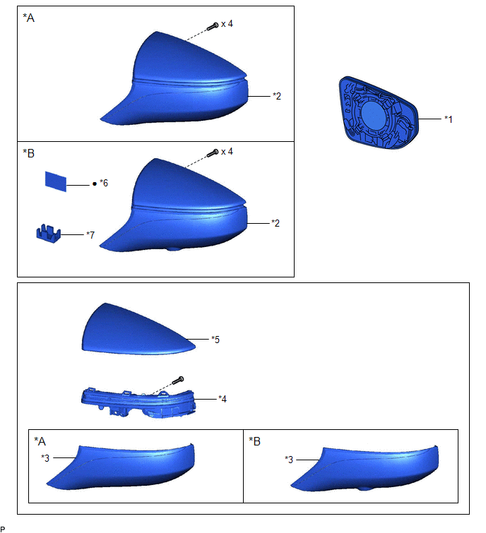
| *A | w/o Panoramic View Monitor System | *B | w/ Panoramic View Monitor System |
| *1 | OUTER MIRROR | *2 | OUTER MIRROR COVER ASSEMBLY |
| *3 | OUTER MIRROR LOWER COVER | *4 | SIDE TURN SIGNAL LIGHT ASSEMBLY |
| *5 | OUTER MIRROR UPPER COVER | *6 | OUTER MIRROR TAPE |
| *7 | CAMERA CONNECTOR CLAMP | - | - |
| ● | Non-reusable part | - | - |
READ NEXT:
 Removal
REMOVAL CAUTION / NOTICE / HINT The necessary procedures (adjustment, calibration, initialization, or registration) that must be performed after parts are removed and installed, or replaced during sid
Inspection
INSPECTION PROCEDURE 1. INSPECT SIDE TURN SIGNAL LIGHT ASSEMBLY LH *a Component without harness connected (Side Turn Signal Light Assembly LH) (a) Apply auxiliary battery voltage to the side
Installation
INSTALLATION CAUTION / NOTICE / HINT HINT:
Use the same procedure for the RH side and LH side.
The following procedure is for the LH side.
PROCEDURE 1. INSTALL SIDE TURN SIGNAL LIGHT ASSEMBLY
SEE MORE:
Drive Motor "A" Position Sensor Internal Electronic Failure (P1CAD49,P1C651F,P1CB038)
DESCRIPTION The motor generator control ECU (MG ECU), which is built into the inverter with converter assembly, monitors its internal operation and detects malfunctions. DTC No. Detection Item DTC Detection Condition Trouble Area MIL Warning Indicate P1C651F Generator Control Modu
Removal
REMOVAL CAUTION / NOTICE / HINT The necessary procedures (adjustment, calibration, initialization, or registration) that must be performed after parts are removed and installed, or replaced during navigation antenna assembly removal/installation are shown below. Necessary Procedure After Parts Remov
© 2016-2026 Copyright www.lexguide.net
