Lexus ES: Adjustment
ADJUSTMENT
CAUTION / NOTICE / HINT
The necessary procedures (adjustment, calibration, initialization or registration) that must be performed after parts are removed and installed, or replaced during park/neutral position switch assembly removal/installation are shown below.
Necessary Procedures After Parts Removed/Installed/Replaced| Replaced Part or Performed Procedure | Necessary Procedure | Effect/Inoperative Function when Necessary Procedure not Performed | Link |
|---|---|---|---|
| Battery terminal is disconnected/reconnected | Perform steering sensor zero point calibration | Lane Control System (for Gasoline Model) | |
| Pre-collision System (for Gasoline Model) | |||
| Parking Support Brake System (for Gasoline Model)*1 | |||
| Lighting System (for Gasoline Model) | |||
| Memorize steering angle neutral point | Parking Assist Monitor System (for Gasoline Model) | | |
| Panoramic View Monitor System (for Gasoline Model) | | ||
| Initialize power trunk lid system | Power Trunk Lid System (for Gasoline Model) | | |
| Replacement of ECM | Vehicle Identification Number (VIN) registration | MIL comes on | |
| ECU communication ID registration (Immobiliser system) | Engine start function | | |
| Replacement of ECM (If transaxle compensation code read from ECM) |
|
| for Initialization: for Registration: |
| Replacement of ECM (If transaxle compensation code not read from ECM) |
| ||
| Replacement of ECM | Code registration (Smart access system with push-button start (for Start Function, Gasoline Model) |
| |
-
*1: When performing learning using the Techstream.
Click here
.gif)
- *2: Not necessary when ECM replaced with new one.
NOTICE:
Before adjusting the park/neutral position switch assembly, check that the shift lever is in N.
PROCEDURE
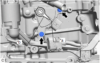
1. SECURE VEHICLE
(a) Fully apply the parking brake and chock a wheel.
CAUTION:
- Make sure to apply the parking brake and chock a wheel before performing this procedure.
- If the vehicle is not secure and the shift lever is moved to N, the vehicle may suddenly move, possibly resulting in an accident or serious injury.
.png)
2. DISCONNECT TRANSMISSION CONTROL CABLE ASSEMBLY
Click here
3. ADJUST PARK/NEUTRAL POSITION SWITCH ASSEMBLY
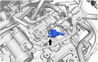
| (a) Disconnect the park/neutral position switch assembly connector. |
|
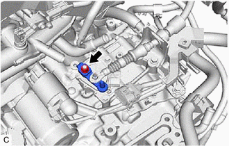
| (b) Remove the nut, washer and transmission control shaft lever from the manual valve lever shaft sub-assembly. |
|
| (c) Loosen the 2 bolts of the park/neutral position switch assembly. |
|
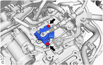
| (d) Align the protrusion with the neutral basic line. |
|
(e) Hold the park/neutral position switch assembly in position and tighten the 2 bolts.
Torque:
5.4 N·m {55 kgf·cm, 48 in·lbf}
(f) Install the transmission control shaft lever to the manual valve lever shaft sub-assembly with the washer and nut.
Torque:
12.7 N·m {130 kgf·cm, 9 ft·lbf}
(g) Connect the park/neutral position switch assembly connector.
4. CONNECT TRANSMISSION CONTROL CABLE ASSEMBLY
Click here
5. INSPECT PARK/NEUTRAL POSITION SWITCH ASSEMBLY
Click here
READ NEXT:
 Components
COMPONENTS ILLUSTRATION *1 BATTERY CLAMP SUB-ASSEMBLY - - N*m (kgf*cm, ft.*lbf): Specified torque - - ILLUSTRATION *1 TRANSMISSION CONTROL CABLE ASSEMBLY *2 TRANSMISS
Inspection
INSPECTION PROCEDURE 1. INSPECT PARK/NEUTRAL POSITION SWITCH ASSEMBLY (a) Measure the resistance according to the value(s) in the table below when the transmission control shaft lever is moved to e
Installation
INSTALLATION PROCEDURE 1. INSTALL PARK/NEUTRAL POSITION SWITCH ASSEMBLY (a) Temporarily install the park/neutral position switch assembly to the automatic transaxle case sub-assembly with the 2 bolts.
SEE MORE:
Voice Guidance does not Function
CAUTION / NOTICE / HINT NOTICE:
Depending on the parts that are replaced during vehicle inspection or maintenance, performing initialization, registration or calibration may be needed. Refer to Precaution for Audio and Visual System.
Click here
When replacing the radio receiver assembly, alw
Removal
REMOVAL CAUTION / NOTICE / HINT The necessary procedures (adjustment, calibration, initialization, or registration) that must be performed after parts are removed and installed, or replaced during telephone antenna assembly removal/installation are shown below. Necessary Procedure After Parts Remove
