Lexus ES: Exhaust Gas Recirculation "A" Flow (P040000-P04029B)
DESCRIPTION
Based on the driving conditions, the ECM regulates the volume of exhaust gas that is recirculated to each engine cylinder in order to lower the combustion temperature and reduce NOx emissions. The ECM monitors signals such as engine speed, engine coolant temperature, electric load, and vehicle speed. When the EGR permission conditions are met, the ECM controls the opening of the EGR valve linearly through signals to the EGR step motor.
| DTC No. | Detection Item | DTC Detection Condition | Trouble Area | MIL | Memory | Note |
|---|---|---|---|---|---|---|
| P040000 | Exhaust Gas Recirculation "A" Flow | During fuel cut, when the change in intake manifold pressure when the EGR valve assembly is operating and when not operating is insufficient (2 trip detection logic). |
| Comes on | DTC stored | SAE Code: P0400 |
| P04019C | Exhaust Gas Recirculation "A" Low / Insufficient Flow | During fuel cut, when the change in intake manifold pressure when the EGR valve assembly is operating and when not operating is insufficient, the intake manifold pressure is less than 41.05 kPa (6.02 psi) when the EGR valve assembly is not operating (1 trip detection logic). |
| Comes on | DTC stored | SAE Code: P0401 |
| P04029B | Exhaust Gas Recirculation "A" High/Excessive Flow | During fuel cut, when the change in intake manifold pressure when the EGR valve assembly is operating and not operating is insufficient, the intake manifold pressure is 41.5 kPa (6.02 psi) or more when the EGR valve assembly is not operating (1 trip detection logic). |
| Comes on | DTC stored | SAE Code: P0402 |
HINT:
DTC P04019C or DTC P04029B will only be stored when DTC P040000 is stored in the second trip.
MONITOR DESCRIPTION
-
P040000
During fuel cut (vehicle being driven with idle ON), when the change in intake manifold pressure when the EGR valve assembly is operating and not operating is insufficient, the ECM determines that the EGR valve is stuck and stores DTC P040000 and illuminates the MIL.
-
P04019C
During fuel cut (vehicle being driven with idle ON), when the change in intake manifold pressure when the EGR valve assembly is operating and not operating is insufficient, the intake manifold pressure is less than the threshold when the EGR valve assembly is not operating, the ECM determines that the flow through the EGR valve is hindered and stores DTC P04019C and illuminates the MIL.
-
P04029B
During fuel cut (vehicle being driven with idle ON), when the change in intake manifold pressure when the EGR valve assembly is operating and not operating is insufficient, the intake manifold pressure is more than the threshold when the EGR valve assembly is not operating, the ECM determines that the flow through the EGR valve is excessive and stores DTC P04029B and illuminates the MIL.
MONITOR STRATEGY
P0400| Related DTC | P0400: EGR valve flow functional |
| Required Sensors/Components (Main) | EGR valve assembly Manifold absolute pressure sensor |
| Required Sensors/Components (Related) | Crankshaft position sensor Camshaft position sensor Vehicle speed sensor Engine coolant temperature sensor Mass air flow meter sub-assembly |
| Frequency of Operation | Once per driving cycle |
| Duration | Within 5 seconds |
| MIL operation | 2 driving cycles |
| Sequence of operation | None |
| Related DTC | P0401: EGR valve low flow rate P0402: EGR valve high flow rate |
| Required Sensors/Components (Main) | EGR valve assembly Manifold absolute pressure sensor |
| Required Sensors/Components (Related) | Crankshaft position sensor Camshaft position sensor Vehicle speed sensor Engine coolant temperature sensor Mass air flow meter sub-assembly |
| Frequency of Operation | Once per driving cycle |
| Duration | Within 5 seconds |
| MIL operation | 1 driving cycle |
| Sequence of operation | Stored when DTC P040000 is stored in the second trip |
TYPICAL ENABLING CONDITIONS
P0400, P0402| Monitor runs whenever the following DTCs are not stored | None |
| Time after engine started | 3 seconds or more |
| Time after engine fuel cut | 2.6 seconds or more |
| Engine speed | 950 to 1600 rpm |
| Vehicle speed | 21 km/h (13 mph) or more |
| Engine coolant temperature | 75°C (167°F) or higher |
| Battery voltage | 11 V or higher |
| Intake air temperature | -10°C (14°F) or higher |
| Atmospheric pressure | 76 kPa(abs) [11 psi(abs)] or higher |
| Monitor runs whenever the following DTCs are not stored | P0010, P1360, P1362, P1364, P1366, P2614 (Motor drive VVT system control module) P0011 (VVT system - advance) P0012 (VVT system - retard) P0013 (Exhaust VVT oil control solenoid) P0014 (Exhaust VVT system - advance) P0015 (Exhaust VVT system - retard) P0016 (VVT system - misalignment) P0017 (Exhaust VVT system - misalignment) P0031, P0032, P101D (Air fuel ratio sensor (sensor 1) heater) P0101, P0102, P0103 (Mass air flow meter) P0106, P0107, P0108 (Manifold absolute pressure) P0111, P0112, P0113 (Intake air temperature sensor) P0116, P0117, P0118 (Engine coolant temperature sensor) P0121, P0122, P0123, P0222, P0223, P2135 (Throttle position sensor) P0125 (Insufficient coolant temperature for closed loop fuel control) P014C, P014D, P015A, P015B, P2195, P2196, P2237, P2238, P2239, P2252, P2253 (Air fuel ratio sensor (sensor 1)) P0171, P0172 (Fuel system) P0327, P0328 (Knock control sensor) P0335, P0337, P0338 (Crankshaft position sensor) P0340, P0342, P0343 (Camshaft position sensor) P0365, P0367, P0368 (Exhaust camshaft position sensor) P0489, P0490 (EGR control circuit) P0500 (Vehicle speed sensor) P0657, P0658, P2102, P2103, P2111, P2112, P2119 (Throttle actuator) P106A (Evaporative emission control system pressure sensor - manifold pressure sensor correlation) P11EA, P11EC, P11ED, P11EE, P11EF, P219A, P219C, P219D, P219E, P219F (Air-fuel ratio imbalance) P2228, P2229 (Atmospheric pressure sensor) |
| Time after engine started | 3 seconds or more |
| Time after engine fuel cut | 2.6 seconds or more |
| Engine speed | 950 to 1600 rpm |
| Vehicle speed | 21 km/h (13 mph) or more |
| Engine coolant temperature | 75°C (167°F) or higher |
| Battery voltage | 11 V or higher |
| Intake air temperature | -10°C (14°F) or higher |
| Atmospheric pressure | 76 kPa(abs) [11 psi(abs)] or higher |
TYPICAL MALFUNCTION THRESHOLDS
P0400| Manifold pressure change* | Less than 1.72 kPa [0.25 psi] (at engine speed 1000 rpm) |
| Manifold pressure change* | Less than 1.72 kPa [0.25 psi] (at engine speed 1000 rpm) |
| Manifold pressure | Less than 41.5 kPa [6.02 psi] |
| Manifold pressure change* | Less than 1.72 kPa [0.25 psi] (at engine speed 1000 rpm) |
| Manifold pressure | 41.5 kPa [6.02 psi] or more |
| *: Calculated by EGR valve open and close | - |
MONITOR RESULT
Refer to detailed information in Checking Monitor Status.
Click here .gif)
| Monitor ID | Test ID | Scaling | Unit | Description |
|---|---|---|---|---|
| $31 | $C0 | Multiply by 0.01 | kPa | Delta manifold absolute pressure |
| Monitor ID | Test ID | Scaling | Unit | Description |
|---|---|---|---|---|
| $31 | $BD | Multiply by 0.01 | kPa | Reference manifold absolute pressure low flow |
| Monitor ID | Test ID | Scaling | Unit | Description |
|---|---|---|---|---|
| $31 | $BE | Multiply by 0.01 | kPa | Reference manifold absolute pressure high flow |
CONFIRMATION DRIVING PATTERN
HINT:
-
After repair has been completed, clear the DTC and then check that the vehicle has returned to normal by performing the following All Readiness check procedure.
Click here
-
When clearing the permanent DTCs, refer to the "CLEAR PERMANENT DTC" procedure.
Click here
- Connect the Techstream to the DLC3.
- Turn the power switch on (IG).
- Turn the Techstream on.
- Clear the DTCs (even if no DTCs are stored, perform the clear DTC procedure).
- Turn the power switch off and wait for at least 30 seconds.
- Turn the power switch on (IG).
- Turn the Techstream on.
-
Put the engine in Inspection Mode (Maintenance Mode).
Click here
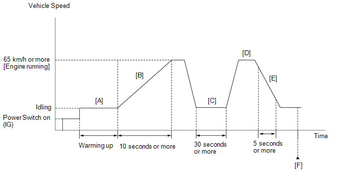
- Start the engine and warm it up until the engine coolant temperature reaches 75°C (167°F) or higher [A].
-
With the engine running, accelerate the vehicle to 65 km/h (40 mph) or more by depressing the accelerator pedal for at least 10 seconds [B].
CAUTION:
When performing the confirmation driving pattern, obey all speed limits and traffic laws.
HINT:
When accelerating the vehicle, depress the accelerator pedal more than normal to start the engine.
- Idle the engine for 30 seconds or more [C].
-
With the shift lever in S and the engine running, accelerate the vehicle to 65 km/h (40 mph) or more [D].
CAUTION:
When performing the confirmation driving pattern, obey all speed limits and traffic laws.
HINT:
If the engine stops, further depress the accelerator pedal to restart the engine.
- Perform the fuel cut operation for 5 seconds or more, with the accelerator pedal fully released [E].
- Enter the following menus: Powertrain / Engine / Trouble Codes [F].
-
Read the pending DTCs.
HINT:
- If a pending DTC is output, the system is malfunctioning.
- If a pending DTC is not output, perform the following procedure.
- Enter the following menus: Powertrain / Engine / Utility / All Readiness.
- Input the DTC P040000, P04019C or P04029B.
-
Check the DTC judgment result.
Techstream Display
Description
NORMAL
- DTC judgment completed
- System normal
ABNORMAL
- DTC judgment completed
- System abnormal
INCOMPLETE
- DTC judgment not completed
- Perform driving pattern after confirming DTC enabling conditions
HINT:
- If the judgment result is NORMAL, the system is normal.
- If the judgment result is ABNORMAL, the system has a malfunction.
- If the judgment result is INCOMPLETE, perform the steps [A] through [F] again.
-
[A] to [F]: Normal judgment procedure.
The normal judgment procedure is used to complete DTC judgment and also used when clearing permanent DTCs.
- When clearing the permanent DTCs, do not disconnect the cable from the auxiliary battery terminal or attempt to clear the DTCs during this procedure, as doing so will clear the universal trip and normal judgment histories.
WIRING DIAGRAM
Refer to DTC P040318.
Click here
CAUTION / NOTICE / HINT
NOTICE:
-
Vehicle Control History may be stored in the hybrid vehicle control ECU assembly if the engine is malfunctioning. Certain vehicle condition information is recorded when Vehicle Control History is stored. Reading the vehicle conditions recorded in both the Freeze Frame Data and Vehicle Control History can be useful for troubleshooting.
Click here
(Select Powertrain in Health Check and then check the time stamp data.)
Click here
-
If any "Engine Malfunction" Vehicle Control History item has been stored in the hybrid vehicle control ECU assembly, make sure to clear it. However, as all Vehicle Control History items are cleared simultaneously, if any Vehicle Control History items other than "Engine Malfunction" are stored, make sure to perform any troubleshooting for them before clearing Vehicle Control History.
Click here
HINT:
- By using the Control the EGR Step Position Active Test, the operation of the EGR valve can be checked.
-
If the EGR valve is normal and is opened using the Active Test, the Data List value changes as follows.
Data List Item
Change in Data List when Number of Steps is Increased Using Control the EGR Step Position Active Test
Intake Manifold Absolute Pressure
Pressure rises
- Read Freeze Frame Data using the Techstream. The ECM records vehicle and driving condition information as Freeze Frame Data the moment a DTC is stored. When troubleshooting, Freeze Frame Data can help determine if the vehicle was moving or stationary, if the engine was warmed up or not, if the air fuel ratio was lean or rich, and other data from the time the malfunction occurred.
PROCEDURE
| 1. | CHECK ANY OTHER DTCS OUTPUT (IN ADDITION TO DTC P040000, P04019C, P04029B) |
(a) Connect the Techstream to the DLC3.
(b) Turn the power switch on (IG).
(c) Turn the Techstream on.
(d) Enter the following menus: Powertrain / Engine / Trouble Codes.
(e) Read the DTCs.
Powertrain > Engine > Trouble Codes| Result | Proceed to |
|---|---|
| DTC P040000, P04019C or P04029B is output | A |
| DTC P040000, P04019C or P04029B and other DTCs are output | B |
HINT:
If any DTCs other than P040000, P04019C or P04029B are output, troubleshoot those DTCs first.
| B | .gif) | GO TO DTC CHART |
|
.gif)
| 2. | READ VALUE USING TECHSTREAM (INTAKE MANIFOLD ABSOLUTE PRESSURE) |
(a) Connect the Techstream to the DLC3.
(b) Turn the power switch on (IG).
(c) Turn the Techstream on.
(d) Enter the following menus: Powertrain / Engine / Data List / Intake Manifold Absolute Pressure.
Powertrain > Engine > Data List| Tester Display |
|---|
| Intake Manifold Absolute Pressure |
(e) Read the value of Intake Manifold Absolute Pressure.
Standard:
| Techstream Display | Specified Condition |
|---|---|
| Intake Manifold Absolute Pressure | 80 to 110 kPa (11.6 to 15.95 psi) |
| NG | | REPLACE MANIFOLD ABSOLUTE PRESSURE SENSOR |
|
| 3. | PERFORM ACTIVE TEST USING TECHSTREAM (CONTROL THE EGR STEP POSITION) |
(a) Connect the Techstream to the DLC3.
(b) Turn the power switch on (IG).
(c) Turn the Techstream on.
(d) Put the engine in Inspection Mode (Maintenance Mode).
Powertrain > Hybrid Control > Utility| Tester Display |
|---|
| Inspection Mode |
(e) Start the engine and warm it up until the engine coolant temperature is 75°C (167°F) or higher.
HINT:
The A/C switch and all accessories should be off.
(f) Enter the following menus: Powertrain / Engine / Active Test / Control the EGR Step Position / Data List / Intake Manifold Absolute Pressure, Coolant Temperature and Engine Independent.
Powertrain > Engine > Active Test| Active Test Display |
|---|
| Control the EGR Step Position |
| Data List Display |
|---|
| Intake Manifold Absolute Pressure |
| Coolant Temperature |
| Engine Independent |
(g) According to the display on the Techstream, compare the values of Data List item Intake Manifold Absolute Pressure before and while performing the Active Test.
NOTICE:
- Make sure that the value of Data List item Engine Independent is "Operate" while performing the Active Test.
- Do not leave the EGR valve open for 10 seconds or more during the Active Test.
- Be sure to return the EGR valve to step 0 when the Active Test is completed.
- Do not open the EGR valve 30 steps or more during the Active Test.
Standard:
The value of Intake Manifold Absolute Pressure changes according to the EGR valve step set by the Active Test.
| Data List | Control the EGR Step Position (Active Test) | ||
|---|---|---|---|
| Before Active Test (Engine idling) | 0 Steps | 0 to 30 Steps (Engine idling) | |
| Intake Manifold Absolute Pressure | 20 to 40 kPa (2.9 to 5.8 psi) | (EGR valve is fully closed) | Intake Manifold Absolute Pressure value is at least +10 kPa (1.45 psi) higher than when EGR valve is fully closed |
HINT:
- If the value of Data List item Engine Independent is "Not Opr" when the engine is idling, charge control is being performed. Perform the Active Test after charge control is complete ("Operate" is displayed).
- While performing the Active Test, if the increase in the value of Intake Manifold Absolute Pressure is small, the EGR valve assembly may be malfunctioning.
- Even if the EGR valve assembly is malfunctioning, rough idling or an increase in the value of Intake Manifold Absolute Pressure may occur while performing the Active Test. However, the amount that the value of Intake Manifold Absolute Pressure increases will be smaller than normal.
| Result | Proceed to |
|---|---|
| Before performing the Active Test (while the engine is idling), the value of Intake Manifold Absolute Pressure is not between 20 to 40 kPa (2.9 to 5.8 psi). | A |
| When performing the Active Test to change the EGR valve step between 0 (EGR valve fully closed) and 30, the value of Intake Manifold Absolute Pressure changes less than 10 kPa (1.45 psi). | B |
| Other than above | C |
| B | | GO TO STEP 6 |
| C | | GO TO STEP 12 |
|
| 4. | CHECK INTAKE SYSTEM |
(a) Check the intake system for vacuum leaks.
Click here
OK:
No leaks from intake system.
HINT:
Perform "Inspection After Repair" after repairing or replacing the intake system.
Click here
| NG | | REPAIR OR REPLACE INTAKE SYSTEM |
|
| 5. | INSPECT EGR VALVE ASSEMBLY |
(a) Remove the EGR valve assembly.
Click here
(b) Check if the EGR valve is stuck open.
OK:
EGR valve is tightly closed.
HINT:
Perform "Inspection After Repair" after replacing the EGR valve assembly.
Click here
| OK | | REPLACE MANIFOLD ABSOLUTE PRESSURE SENSOR |
| NG | | REPLACE EGR VALVE ASSEMBLY |
| 6. | REPLACE EGR VALVE ASSEMBLY |
(a) Replace the EGR valve assembly.
Click here
HINT:
Perform "Inspection After Repair" after replacing the EGR valve assembly.
Click here
|
| 7. | CLEAR DTC |
(a) Connect the Techstream to the DLC3.
(b) Turn the power switch on (IG).
(c) Turn the Techstream on.
(d) Clear the DTCs.
Powertrain > Engine > Clear DTCs(e) Turn the power switch off and wait for at least 30 seconds.
|
| 8. | CHECK WHETHER DTC OUTPUT RECURS (DTC P040000, P04019C OR P04029B) |
(a) Drive the vehicle in accordance with the driving pattern described in Confirmation Driving Pattern.
(b) Enter the following menus: Powertrain / Engine / Utility / All Readiness.
Powertrain > Engine > Utility| Tester Display |
|---|
| All Readiness |
(c) Input the DTC: P040000, P04019C or P04029B.
(d) Check the DTC judgment result.
| Result | Proceed to |
|---|---|
| NORMAL (DTCs are not output) | A |
| ABNORMAL (DTC P040000, P04019C or P04029B is output) | B |
| A | | END |
|
| 9. | REPLACE EGR COOLER ASSEMBLY |
(a) Replace the EGR cooler assembly.
Click here
HINT:
- If any of the EGR system related pipes (EGR pipe, exhaust manifold, etc.) are cracked, damaged or clogged, replace them as necessary.
-
Perform "Inspection After Repair" after replacing the EGR system.
Click here
|
| 10. | CLEAR DTC |
(a) Connect the Techstream to the DLC3.
(b) Turn the power switch on (IG).
(c) Turn the Techstream on.
(d) Clear the DTCs.
Powertrain > Engine > Clear DTCs(e) Turn the power switch off and wait for at least 30 seconds.
|
| 11. | CHECK WHETHER DTC OUTPUT RECURS (DTC P040000, P04019C OR P04029B) |
(a) Drive the vehicle in accordance with the driving pattern described in Confirmation Driving Pattern.
(b) Enter the following menus: Powertrain / Engine / Utility / All Readiness.
Powertrain > Engine > Utility| Tester Display |
|---|
| All Readiness |
(c) Input the DTC: P040000, P04019C or P04029B.
(d) Check the DTC judgment result.
| Techstream Display | Description |
|---|---|
| NORMAL |
|
| ABNORMAL |
|
| INCOMPLETE |
|
| NEXT | | END |
| 12. | CLEAR DTC |
(a) Connect the Techstream to the DLC3.
(b) Turn the power switch on (IG).
(c) Turn the Techstream on.
(d) Clear the DTCs.
Powertrain > Engine > Clear DTCs(e) Turn the power switch off and wait for at least 30 seconds.
|
| 13. | CHECK WHETHER DTC OUTPUT RECURS (DTC P040000, P04019C OR P04029B) |
(a) Drive the vehicle in accordance with the driving pattern described in Confirmation Driving Pattern.
(b) Enter the following menus: Powertrain / Engine / Utility / All Readiness.
Powertrain > Engine > Utility| Tester Display |
|---|
| All Readiness |
(c) Input the DTC: P040000, P04019C or P04029B.
(d) Check the DTC judgment result.
| Result | Proceed to |
|---|---|
| NORMAL (DTCs are not output) | A |
| ABNORMAL (DTC P040000, P04019C or P04029B is output) | B |
HINT:
Perform "Inspection After Repair" after replacing the EGR valve assembly.
Click here
| A | | END |
| B | | REPLACE EGR VALVE ASSEMBLY |
READ NEXT:
 Exhaust Gas Recirculation "A" Circuit Current Below Threshold (P040318,P040319,P140018,P140019)
DESCRIPTION Refer to DTC P040000. Click here DTC No. Detection Item DTC Detection Condition Trouble Area MIL Memory Note P040318 Exhaust Gas Recirculation "A" Circuit Current B
Evaporative Emission System Leak Detection Reference Orifice Low Flow (P043E00,P043F00,P24007E,P24007F,P24187E)
DTC SUMMARY DTC No. Detection Item DTC Detection Condition Trouble Area MIL Memory Note P043E00 Evaporative Emission System Leak Detection Reference Orifice Low Flow Reference o
Catalyst System Efficiency Below Threshold Bank 1 (P042000)
MONITOR DESCRIPTION The ECM uses air fuel ratio sensors mounted in front of and behind the Three-Way Catalytic Converter (TWC) to monitor its efficiency. The first sensor, the air fuel ratio sensor (s
SEE MORE:
Collision detected or Collision Sensor Connection (Open) (P160600,P160604)
DTC SUMMARY MALFUNCTION DESCRIPTION The hybrid vehicle control ECU and airbag ECU assembly detect that a collision has occurred and shut off the system main relay. The cause of this DTC may be one of the following:
Collision is detected
Detection sensor system malfunction
Airbag system malfu
Steering Pad Switch Circuit
DESCRIPTION This circuit sends an operation signal from the steering pad switch assembly to the radio receiver assembly. If there is an open in the circuit, the navigation system cannot be operated using the steering pad switch assembly. If there is a short in the circuit, the same condition as when
