
Lexus ES: Installation
INSTALLATION
PROCEDURE
1. INSTALL REAR BUMPER ASSEMBLY
(a) w/ Wire Harness:
(1) Connect the connector.
(b) Engage the 6 claws as shown in the illustration.
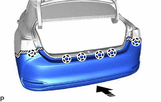
.png) | Install in this Direction |
(c) Engage the 6 claws as shown in the illustration.
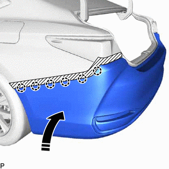
| | Install in this Direction |
HINT:
Use the same procedure for the RH side and LH side.
(d) Install the 12 clips.
(e) Install the screw.
HINT:
Use the same procedure for the RH side and LH side.
(f) Engage the 2 claws.
HINT:
Use the same procedure for the RH side and LH side.
(g) Install the clip.
HINT:
Use the same procedure for the RH side and LH side.
(h) Install the rear bumper assembly with the 2 screws.
2. INSTALL REAR COMBINATION LIGHT COVER LH
Click here .gif)
3. INSTALL REAR COMBINATION LIGHT COVER RH
HINT:
Use the same procedure as for the LH side.
4. CONNECT CABLE TO NEGATIVE AUXILIARY BATTERY TERMINAL (w/ Hands Free Power Trunk Lid)
Click here
5. INITIALIZE KICK DOOR CONTROL SENSOR (w/ Hands Free Power Trunk Lid)
Click here
6. INSPECT KICK DOOR CONTROL SENSOR (w/ Hands Free Power Trunk Lid)
Click here
7. PERFORM CALIBRATION (w/ Parking Support Brake System)
Click here
READ NEXT:
 Components
COMPONENTS ILLUSTRATION *1 COURTESY LIGHT ASSEMBLY *2 REAR DOOR TRIM BOARD SUB-ASSEMBLY *3 REAR DOOR UPPER TRIM PAD *4 REAR POWER WINDOW REGULATOR SWITCH ASSEMBLY WITH REAR DOOR UP
Removal
REMOVAL CAUTION / NOTICE / HINT The necessary procedures (adjustment, calibration, initialization, or registration) that must be performed after parts are removed and installed, or replaced during rea
SEE MORE:
Rear Window Defogger System does not Operate
DESCRIPTION When the rear window defogger switch on the air conditioning control assembly is pressed, the operation signal is transmitted to the air conditioning amplifier assembly via LIN communication. When the air conditioning amplifier assembly receives the signal, it turns on the DEF relay to o
Installation
INSTALLATION CAUTION / NOTICE / HINT HINT:
Use the same procedure for the RH side and LH side.
The following procedure is for the LH side.
PROCEDURE 1. INSTALL REAR SUSPENSION ARM BRACKET (a) Temporarily install the rear suspension arm bracket to the rear trailing arm assembly with the bo
