Lexus ES: Reassembly
REASSEMBLY
PROCEDURE
1. INSTALL GENERATOR ROTOR BEARING
| (a) Using SST and a press, install a new generator rotor bearing. SST: 09950-60011 09951-00470 SST: 09950-70010 09951-07100 |
|
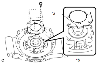
| (b) Fit the tabs of the retainer plate into the cutouts of the generator drive end frame to install the retainer plate. |
|
(c) Install the 4 screws.
Torque:
2.3 N·m {23 kgf·cm, 20 in·lbf}
2. INSTALL GENERATOR ROTOR ASSEMBLY
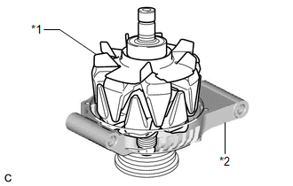
(a) Place the generator drive end frame on the generator pulley with clutch.
| (b) Install the generator rotor assembly to the generator drive end frame. |
|
3. INSTALL GENERATOR COIL ASSEMBLY
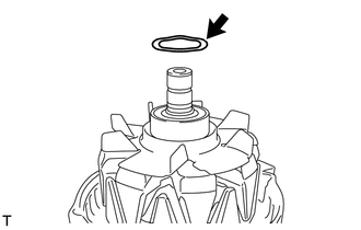
| (a) Place a new washer on the generator rotor assembly. |
|
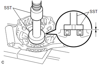
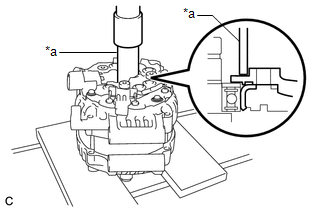
| (b) Using a 21 mm deep socket wrench and press, slowly press in the generator coil assembly. |
|
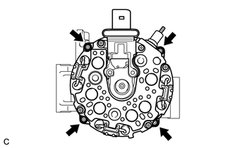
| (c) Install the 4 bolts. Torque: 5.9 N·m {60 kgf·cm, 52 in·lbf} |
|
4. INSTALL GENERATOR BRUSH HOLDER ASSEMBLY
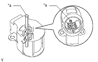
| (a) While pushing the 2 brushes into the generator brush holder assembly, insert a 1.0 mm (0.0394 in.) pin into the generator brush holder assembly hole. |
|
(b) Install the generator brush holder assembly to the generator coil assembly with the 2 screws.
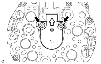
| *a | Pin (1.0 mm) |
.png) | Pull out |
Torque:
1.8 N·m {18 kgf·cm, 16 in·lbf}
(c) Pull out the pin from the generator brush holder assembly hole.
5. INSTALL GENERATOR TERMINAL INSULATOR
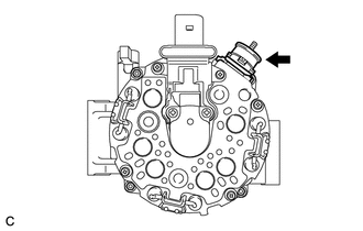
(a) Install the generator terminal insulator to the generator coil assembly.
NOTICE:
Be sure to install the generator terminal insulator in the correct orientation.
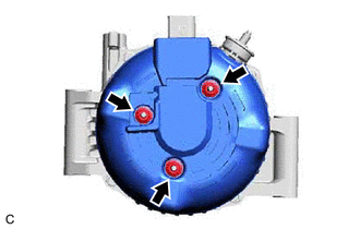
6. INSTALL GENERATOR REAR END COVER
| (a) Install the generator rear end cover to the generator coil assembly with the 3 nuts. Torque: 4.6 N·m {47 kgf·cm, 41 in·lbf} |
|
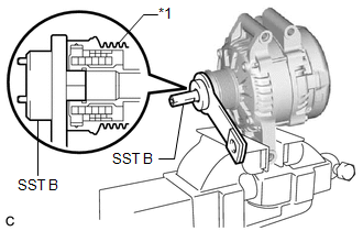
7. INSTALL GENERATOR PULLEY WITH CLUTCH
(a) Secure the generator drive end frame in a vise between aluminum plates.
(b) Temporarily install a new generator pulley with clutch to the rotor shaft.
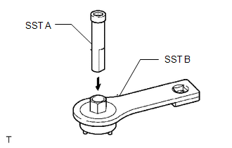
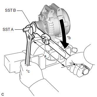
| (c) Install SST (A) to SST (B) as shown in the illustration. SST: 09820-63021 |
|
| (d) Fit the rotor shaft end into SST (A). |
|
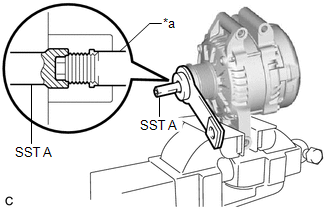
| (e) Fit SST (B) to the generator pulley with clutch. |
|
| (f) Tighten the generator pulley with clutch by turning SST (B) as shown in the illustration. Torque: Specified tightening torque : 80 N·m {816 kgf·cm, 59 ft·lbf} NOTICE:
HINT:
|
|
.gif)
(g) Remove SST (A) and (B) from the generator pulley with clutch.
(h) Check that the generator pulley with clutch rotates smoothly.
(i) Remove the generator drive end frame from the vise.
8. INSTALL GENERATOR PULLEY CAP
(a) Install a new generator pulley cap to the generator pulley with clutch.
READ NEXT:
 Inspection
INSPECTION PROCEDURE 1. INSPECT GENERATOR BRUSH HOLDER ASSEMBLY (a) Using a vernier caliper, measure the length of the exposed brushes. Standard Exposed Brush Length: 9.5 to 11.5 mm (0.374 to 0.45
Disassembly
DISASSEMBLY PROCEDURE 1. REMOVE GENERATOR PULLEY CAP (a) Remove the generator pulley cap from the generator pulley with clutch. NOTICE:
Do not reuse the generator pulley cap.
If the generato
On-vehicle Inspection
ON-VEHICLE INSPECTION CAUTION / NOTICE / HINT NOTICE:
Do not remove the generator pulley cap.
If the generator pulley cap is removed, replace the generator pulley cap and generator pulley with cl
SEE MORE:
Components
COMPONENTS ILLUSTRATION *1 CLUTCH DRUM OIL SEAL RING *2 FRONT OIL PUMP BODY *3 FRONT OIL PUMP DRIVE GEAR *4 FRONT OIL PUMP DRIVEN GEAR *5 OIL STRAINER ASSEMBLY *6 RING PIN *7 STATOR SHAFT ASSEMBLY *8 FRONT OIL PUMP COVER SUB-ASSEMBLY Tightening torque f
Components
COMPONENTS ILLUSTRATION *1 ENGINE WIRE *2 HV AIR CONDITIONING WIRE *3 STARTER HOLE INSULATOR *4 FLYWHEEL HOUSING SIDE COVER *5 FUEL DELIVERY GUARD *6 STEERING GEAR HEAT INSULATOR N*m (kgf*cm, ft.*lbf): Specified torque - - ILLUSTRATION *1 FRONT FRAME
