Lexus ES: Components
COMPONENTS
ILLUSTRATION
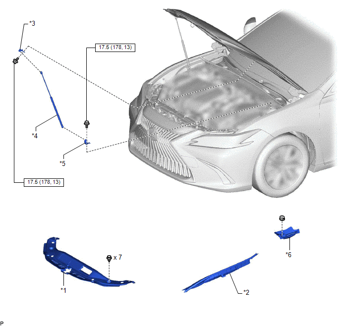
| *1 | COOL AIR INTAKE DUCT SEAL | *2 | FRONT FENDER SPLASH SHIELD SUB-ASSEMBLY |
| *3 | HOOD STAY BRACKET | *4 | HOOD SUPPORT ASSEMBLY |
| *5 | HOOD SUPPORT BRACKET | *6 | NO. 3 COWL TOP PANEL INSULATOR |
.png) | N*m (kgf*cm, ft.*lbf): Specified torque | - | - |
READ NEXT:
 Removal
REMOVAL CAUTION / NOTICE / HINT HINT:
Use the same procedure for the RH side and LH side.
The following procedure is for the LH side.
PROCEDURE 1. REMOVE HOOD SUPPORT ASSEMBLY NOTICE:
Avoid
Installation
INSTALLATION CAUTION / NOTICE / HINT HINT:
Use the same procedure for the RH side and LH side.
The following procedure is for the LH side.
PROCEDURE 1. INSTALL HOOD SUPPORT BRACKET (a) Engage
Disposal
DISPOSAL PROCEDURE 1. DISPOSE OF HOOD SUPPORT ASSEMBLY (a) Secure the hood support assembly horizontally in a vise with the piston rod pulled out. (b) Wearing safety glasses, gradually cut a part w
SEE MORE:
Installation
INSTALLATION CAUTION / NOTICE / HINT HINT:
Use the same procedure for the RH side and LH side.
The following procedure is for the LH side.
PROCEDURE 1. PRECAUTION NOTICE: After turning the engine switch (for Gasoline Model) or power switch (for HV Model) off, waiting time may be required bef
Generator Position Sensor Circuit "A" Circuit Voltage Below Threshold (P0C6416,P0C6417,P0C6916,P0C6917)
DTC SUMMARY MALFUNCTION DESCRIPTION These DTCs indicate an abnormal resolver output signal. The cause of this malfunction may be one of the following: Internal inverter malfunction
Inverter with converter assembly internal circuit malfunction
Inverter low-voltage circuit malfunction
The con
© 2016-2026 Copyright www.lexguide.net
