Lexus ES: Reassembly
REASSEMBLY
PROCEDURE
1. INSTALL RING PIN
| (a) Install the 2 ring pins to the front oil pump cover sub-assembly. |
|
.png)
2. INSTALL FRONT OIL PUMP BODY
| (a) Install the front oil pump body to the front oil pump cover sub-assembly. |
|
.png)
3. INSTALL FRONT OIL PUMP DRIVEN GEAR
| (a) Coat the front oil pump driven gear with Toyota Genuine ATF WS and install it to the front oil pump body. |
|
.png)
4. INSTALL FRONT OIL PUMP DRIVE GEAR
.png)
(a) Coat the front oil pump drive gear with Toyota Genuine ATF WS and install it to the front oil pump body.
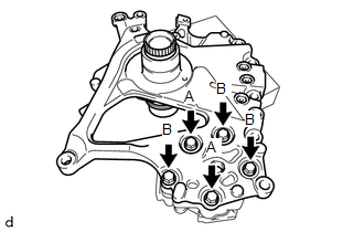
5. INSTALL STATOR SHAFT ASSEMBLY
| (a) Install the stator shaft assembly to the front oil pump body with the 5 bolts. Torque: 9.1 N·m {93 kgf·cm, 81 in·lbf} Bolt Length:
|
|
6. INSTALL OIL STRAINER ASSEMBLY
| (a) Using a T30 "TORX" socket wrench, install a new oil strainer assembly to the front oil pump cover sub-assembly with the 2 bolts. Torque: 5.4 N·m {55 kgf·cm, 48 in·lbf} |
|
.png)
7. INSTALL CLUTCH DRUM OIL SEAL RING
| (a) Apply a small amount of MP grease to the entire circumference of the clutch drum oil seal ring installation groove portion. HINT: By applying MP grease, the wobble within the clutch drum oil seal ring installation groove will be eliminated, preventing damage to the clutch drum oil seal ring at the time of front oil pump assembly installation. |
|
.png)
(b) Coat 4 new clutch drum oil seal rings with Toyota Genuine ATF WS and install them to the front oil pump assembly.
NOTICE:
While making the spread of the opening of the clutch drum oil seal ring as small as possible, install it to the front oil pump assembly.
If the ring opening is spread, briefly hold it closed with your fingers to return it to its original condition.
READ NEXT:
 Adjustment
ADJUSTMENT CAUTION / NOTICE / HINT The necessary procedures (adjustment, calibration, initialization or registration) that must be performed after parts are removed and installed, or replaced during p
Components
COMPONENTS ILLUSTRATION *1 BATTERY CLAMP SUB-ASSEMBLY - - N*m (kgf*cm, ft.*lbf): Specified torque - - ILLUSTRATION *1 TRANSMISSION CONTROL CABLE ASSEMBLY *2 TRANSMISS
SEE MORE:
Open in One Side of Bus 3 Branch Line
DESCRIPTION When the CAN bus main lines are normal (no open, short to ground, short to +B or short between lines) and there is an ECU or sensor on the "Communication Bus Check" screen that is indicated as not communicating or whose connection status on the "Communication Bus Check" screen changes in
Inspection
INSPECTION PROCEDURE 1. INSPECT FUEL SENDER GAUGE ASSEMBLY CAUTION: Perform the inspection in a well-ventilated area. Do not perform the inspection near an open flame. (a) Check that the float moves smoothly between F and E. (b) Check the fuel sender gauge assembly voltage. (1) Apply 5 V between
