Lexus ES: Rear Television Camera Communication Stop Mode
DESCRIPTION
| Detection Item | Symptom | Trouble Area |
|---|---|---|
| Rear Television Camera Communication Stop Mode | Any of the following conditions are met:
|
|
WIRING DIAGRAM
w/ Panoramic View Monitor System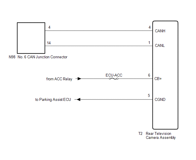 w/o Panoramic View Monitor System
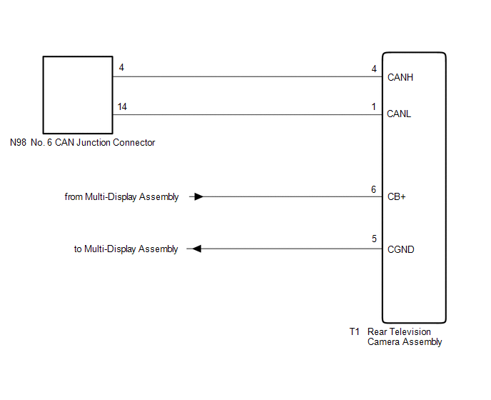
CAUTION / NOTICE / HINT
CAUTION:
When performing the confirmation driving pattern, obey all speed limits and traffic laws.
NOTICE:
-
Because the order of diagnosis is important to allow correct diagnosis, make sure to begin troubleshooting using How to Proceed with Troubleshooting when CAN communication system related DTCs are output.
Click here
.gif)
- Before measuring the resistance of the CAN bus, turn the power switch off and leave the vehicle for 1 minute or more without operating the key or any switches, or opening or closing the doors. After that, disconnect the cable from the negative (-) auxiliary battery terminal and leave the vehicle for 1 minute or more before measuring the resistance.
-
After turning the power switch off, waiting time may be required before disconnecting the cable from the negative (-) auxiliary battery terminal. Therefore, make sure to read the disconnecting the cable from the negative (-) auxiliary battery terminal notices before proceeding with work.
Click here
-
After performing repairs, perform the DTC check procedure and confirm that the DTCs are not output again.
DTC check procedure: Turn the power switch on (IG) and wait for 1 minute or more. Then operate the suspected malfunctioning system and drive the vehicle at 60 km/h (37 mph) or more for 5 minutes or more.
-
After the repair, perform the CAN bus check and check that all the ECUs and sensors connected to the CAN communication system are displayed as normal.
Click here
- Inspect the fuses for circuits related to this system before performing the following procedure.
HINT:
- Before disconnecting related connectors for inspection, push in on each connector body to check that the connector is not loose or disconnected.
- When a connector is disconnected, check that the terminals and connector body are not cracked, deformed or corroded.
PROCEDURE
| 1. | CHECK VEHICLE TYPE |
(a) Check vehicle type.
| Result | Proceed to |
|---|---|
| w/ Panoramic View Monitor System | A |
| w/o Panoramic View Monitor System | B |
| B | .gif) | GO TO STEP 4 |
|
.gif)
| 2. | CHECK FOR OPEN IN CAN BUS LINES (REAR TELEVISION CAMERA ASSEMBLY BRANCH LINE) |
(a) Disconnect the cable from the negative (-) auxiliary battery terminal.
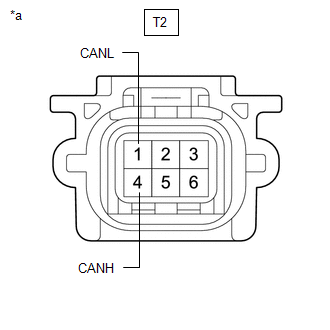
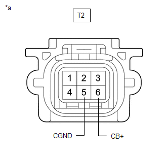
(b) Disconnect the T2 rear television camera assembly connector.
| (c) Measure the resistance according to the value(s) in the table below. Standard Resistance:
|
|
| NG | | REPAIR OR REPLACE CAN BRANCH LINES OR CONNECTOR (REAR TELEVISION CAMERA ASSEMBLY) |
|
| 3. | CHECK HARNESS AND CONNECTOR (POWER SOURCE CIRCUIT) |
| (a) Measure the resistance according to the value(s) in the table below. Standard Resistance:
|
|
(b) Reconnect the cable to the negative (-) auxiliary battery terminal.
(c) Measure the voltage according to the value(s) in the table below.
Standard Voltage:
| Tester Connection | Condition | Specified Condition |
|---|---|---|
| T2-6 (CB+) - Body ground | Power switch on (ACC) | 5.5 to 7.05 V |
| OK | | REPLACE REAR TELEVISION CAMERA ASSEMBLY |
| NG | | REPAIR OR REPLACE HARNESS OR CONNECTOR (POWER SOURCE CIRCUIT) |
| 4. | CHECK FOR OPEN IN CAN BUS LINES (REAR TELEVISION CAMERA ASSEMBLY BRANCH LINE) |
(a) Disconnect the cable from the negative (-) auxiliary battery terminal.
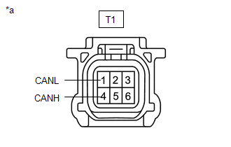
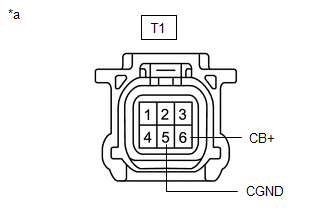
(b) Disconnect the T1 rear television camera assembly connector.
| (c) Measure the resistance according to the value(s) in the table below. Standard Resistance:
|
|
| NG | | REPAIR OR REPLACE CAN BRANCH LINES OR CONNECTOR (REAR TELEVISION CAMERA ASSEMBLY) |
|
| 5. | CHECK HARNESS AND CONNECTOR (POWER SOURCE CIRCUIT) |
| (a) Measure the resistance according to the value(s) in the table below. Standard Resistance:
|
|
(b) Reconnect the cable to the negative (-) auxiliary battery terminal.
(c) Measure the voltage according to the value(s) in the table below.
Standard Voltage:
| Tester Connection | Condition | Specified Condition |
|---|---|---|
| T1-6 (CB+) - Body ground | Power switch on (ACC) | 5.5 to 7.05 V |
| OK | | REPLACE REAR TELEVISION CAMERA ASSEMBLY |
| NG | | REPAIR OR REPLACE HARNESS OR CONNECTOR (POWER SOURCE CIRCUIT) |
READ NEXT:
 Motor Generator Control ECU Communication Stop Mode
DESCRIPTION Detection Item Symptom Trouble Area Motor Generator Control ECU Communication Stop Mode Any of the following conditions are met:
Communication stop for "Motor Generator" is
Millimeter Wave Radar Sensor Communication Stop Mode
DESCRIPTION Detection Item Symptom Trouble Area Millimeter Wave Radar Sensor Communication Stop Mode Any of the following conditions are met:
Communication stop for "Front Radar" is in
Headup Display Communication Stop Mode
DESCRIPTION Detection Item Symptom Trouble Area Headup Display Communication Stop Mode Any of the following conditions are met:
Communication stop for "Head Up Display" is indicated on
SEE MORE:
Remote Up / Down Function does not Operate
DESCRIPTION When the power switch on (IG), the multiplex network master switch assembly sends remote up and down signals to each power window regulator motor assembly via LIN communication. WIRING DIAGRAM CAUTION / NOTICE / HINT NOTICE:
The power window control system uses the LIN communication
Components
COMPONENTS ILLUSTRATION *1 FUEL DELIVERY PIPE RH *2 FUEL DELIVERY PIPE WITH SENSOR ASSEMBLY LH *3 DIRECT FUEL INJECTOR ASSEMBLY *4 FUEL INJECTOR SEAL *5 NO. 2 FUEL PIPE SUB-ASSEMBLY *6 WIRE HARNESS CLAMP BRACKET *7 NO. 3 FUEL INJECTOR BACK-UP RING *8 O-RING
