Lexus ES: Headup Display Communication Stop Mode
DESCRIPTION
| Detection Item | Symptom | Trouble Area |
|---|---|---|
| Headup Display Communication Stop Mode | Any of the following conditions are met:
|
|
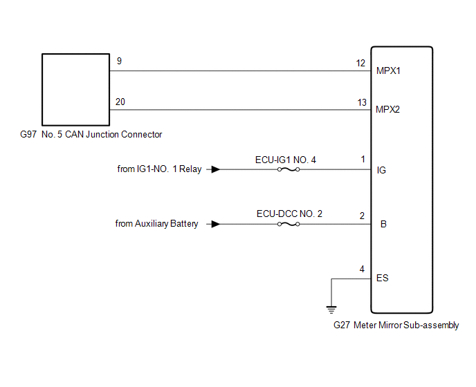
WIRING DIAGRAM
CAUTION / NOTICE / HINT
CAUTION:
When performing the confirmation driving pattern, obey all speed limits and traffic laws.
NOTICE:
-
Because the order of diagnosis is important to allow correct diagnosis, make sure to begin troubleshooting using How to Proceed with Troubleshooting when CAN communication system related DTCs are output.
Click here
.gif)
- Before measuring the resistance of the CAN bus, turn the power switch off and leave the vehicle for 1 minute or more without operating the key or any switches, or opening or closing the doors. After that, disconnect the cable from the negative (-) auxiliary battery terminal and leave the vehicle for 1 minute or more before measuring the resistance.
-
After turning the power switch off, waiting time may be required before disconnecting the cable from the negative (-) auxiliary battery terminal. Therefore, make sure to read the disconnecting the cable from the negative (-) auxiliary battery terminal notices before proceeding with work.
Click here
-
After performing repairs, perform the DTC check procedure and confirm that the DTCs are not output again.
DTC check procedure: Turn the power switch on (IG) and wait for 1 minute or more. Then operate the suspected malfunctioning system and drive the vehicle at 60 km/h (37 mph) or more for 5 minutes or more.
-
After the repair, perform the CAN bus check and check that all the ECUs and sensors connected to the CAN communication system are displayed as normal.
Click here
- Inspect the fuses for circuits related to this system before performing the following procedure.
HINT:
- Before disconnecting related connectors for inspection, push in on each connector body to check that the connector is not loose or disconnected.
- When a connector is disconnected, check that the terminals and connector body are not cracked, deformed or corroded.
PROCEDURE
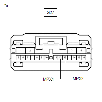
| 1. | CHECK FOR OPEN IN CAN BUS LINES (METER MIRROR SUB-ASSEMBLY BRANCH LINE) |
(a) Disconnect the cable from the negative (-) auxiliary battery terminal.
(b) Disconnect the G27 meter mirror sub-assembly connector.
| (c) Measure the resistance according to the value(s) in the table below. Standard Resistance:
|
|
| NG | .gif) | REPAIR OR REPLACE CAN BRANCH LINES OR CONNECTOR (METER MIRROR SUB-ASSEMBLY) |
|
.gif)
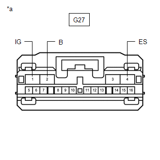
| 2. | CHECK HARNESS AND CONNECTOR (POWER SOURCE CIRCUIT) |
| (a) Measure the resistance according to the value(s) in the table below. Standard Resistance:
|
|
(b) Reconnect the cable to the negative (-) auxiliary battery terminal.
(c) Measure the voltage according to the value(s) in the table below.
Standard Voltage:
| Tester Connection | Condition | Specified Condition |
|---|---|---|
| G27-1 (IG) - Body ground | Power switch on (IG) | 11 to 14 V |
| G27-2 (B) - Body ground | Power switch off | 11 to 14 V |
| OK | | REPLACE METER MIRROR SUB-ASSEMBLY |
| NG | | REPAIR OR REPLACE HARNESS OR CONNECTOR (POWER SOURCE CIRCUIT) |
READ NEXT:
 Door Mirror ECU RH Communication Stop Mode
DESCRIPTION Detection Item Symptom Trouble Area Door Mirror ECU RH Communication Stop Mode Any of the following conditions are met:
Communication stop for "Front Door RH/R-Mirror (FR-D
Door Mirror ECU LH Communication Stop Mode
DESCRIPTION Detection Item Symptom Trouble Area Door Mirror ECU LH Communication Stop Mode Any of the following conditions are met:
Communication stop for "Front Door LH/L-Mirror (FL-D
Driver Seat Control ECU Communication Stop Mode
DESCRIPTION Detection Item Symptom Trouble Area Driver Seat Control ECU Communication Stop Mode Any of the following conditions are met:
Communication stop for "D-Seat" is indicated on
SEE MORE:
Hybrid/EV Battery "A" Voltage Sensor/Boosting Converter Voltage Sensor "A" Signal Compare Failure (P1C2D62)
DTC SUMMARY MALFUNCTION DESCRIPTION The hybrid vehicle control ECU detects a VB sensor or VL sensor malfunction. The cause of this malfunction may be one of the following: Inverter voltage (VB or VL) sensor internal circuit malfunction
Voltage sensor malfunction
Motor generator control ECU (MG
Portable Player cannot be Connected Manually/Automatically
CAUTION / NOTICE / HINT HINT: Some versions of "Bluetooth" compatible audio players may not function properly, or the functions may be limited using the radio receiver assembly, even if the portable audio player itself can play files. Click here PROCEDURE 1. CHECK CONNECTED DEVICE SETTINGS
