Lexus ES: Components
COMPONENTS
ILLUSTRATION
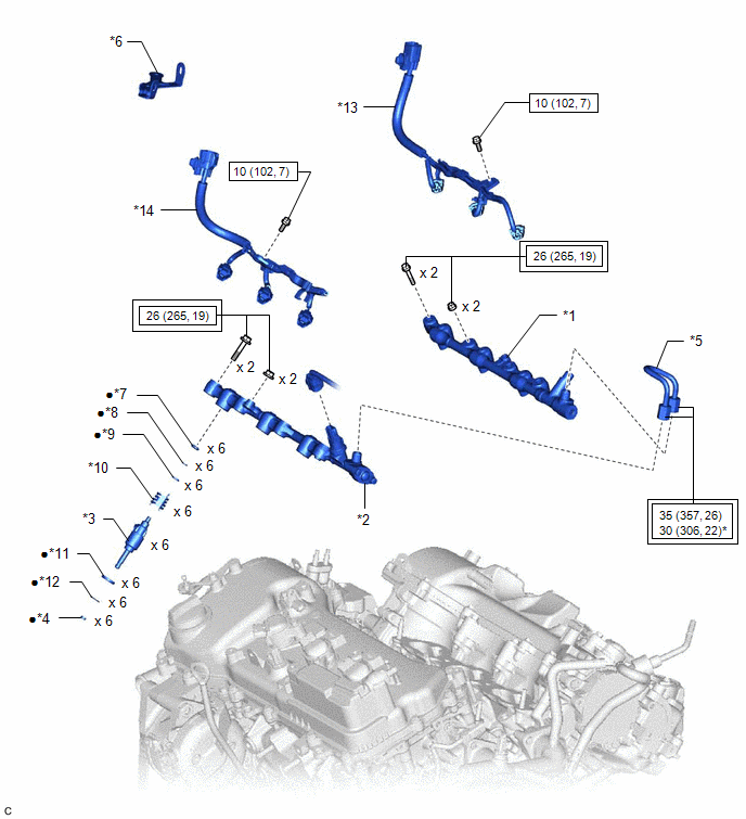
| *1 | FUEL DELIVERY PIPE RH | *2 | FUEL DELIVERY PIPE WITH SENSOR ASSEMBLY LH |
| *3 | DIRECT FUEL INJECTOR ASSEMBLY | *4 | FUEL INJECTOR SEAL |
| *5 | NO. 2 FUEL PIPE SUB-ASSEMBLY | *6 | WIRE HARNESS CLAMP BRACKET |
| *7 | NO. 3 FUEL INJECTOR BACK-UP RING | *8 | O-RING |
| *9 | NO. 1 FUEL INJECTOR BACK-UP RING | *10 | NOZZLE HOLDER CLAMP |
| *11 | INJECTOR VIBRATION INSULATOR | *12 | C-RING |
| *13 | NO. 6 ENGINE WIRE | *14 | NO. 7 ENGINE WIRE |
.png) | Tightening torque for "Major areas involving basic vehicle performance such as moving/turning/stopping": N*m (kgf*cm, ft.*lbf) | .png) | N*m (kgf*cm, ft.*lbf): Specified torque |
| * | For use with a union nut wrench | ● | Non-reusable part |
READ NEXT:
 Removal
REMOVAL CAUTION / NOTICE / HINT The necessary procedures (adjustment, calibration, initialization or registration) that must be performed after parts are removed and installed, or replaced during dire
Inspection
INSPECTION PROCEDURE 1. INSPECT DIRECT FUEL INJECTOR ASSEMBLY NOTICE: This inspection is for checking the direct fuel injector assembly for an open or short. Because the direct fuel injector assembly
Installation
INSTALLATION PROCEDURE 1. INSTALL FUEL INJECTOR SEAL (a) Apply engine conditioner to the area shown in the illustration. Using a piece of cloth, clean carbon deposits from the direct fuel injector
SEE MORE:
Vehicle Control History
VEHICLE CONTROL HISTORY NOTICE: Make sure to record any output Vehicle Control History codes before clearing them and checking the Vehicle Control History again. CHECK VEHICLE CONTROL HISTORY (LANE CONTROL SYSTEM) (a) Connect the Techstream to the DLC3. (b) Turn the engine switch on (IG). (c) Turn t
EPB High Temperature (C13AA)
DESCRIPTION If the electric parking brake is used continuously, system operation is stopped to prevent the parking brake actuator assembly from overheating. This DTC is stored when system operation is stopped to prevent the parking brake actuator assembly from overheating and is not a malfunction.
© 2016-2026 Copyright www.lexguide.net
