Lexus ES: Pressure Control Solenoid "L" Circuit Short to Ground or Open (P08BA14)
DESCRIPTION
Refer to DTC P08BA12.
Click here .gif)
| DTC No. | Detection Item | DTC Detection Condition | Trouble Area | MIL | Memory | Note |
|---|---|---|---|---|---|---|
| P08BA14 | Pressure Control Solenoid "L" Circuit Short to Ground or Open | While the vehicle is being driven so that gear changes occur, a short to ground or open is detected in the solenoid (SL6) valve circuit for 1 second (1-trip detection logic). |
| Comes on | DTC stored | SAE Code: P08C1 |
MONITOR DESCRIPTION
This DTC indicates an open or short to ground in the solenoid (SL6) valve circuit. The ECM commands gear shifts by turning the solenoid valves on or off. When there is an open or short in any solenoid valve circuit, the ECM detects the problem, illuminates the MIL and stores a DTC.
The ECM performs the fail-safe function and turns the other normal solenoid valves on or off. In the case of an open or short circuit, the ECM stops sending current to the open or shorted solenoid.
MONITOR STRATEGY
| Related DTCs | P08C1: Solenoid (SL6) valve/Range check (Low voltage) |
| Required sensors/components | Solenoid (SL6) valve |
| Frequency of operation | Continuous |
| Duration | 1 sec. |
| MIL operation | Immediate |
| Sequence of operation | None |
TYPICAL ENABLING CONDITIONS
| The monitor will run whenever the following DTCs are not stored | None |
| Solenoid current cut status | Not cut |
| Engine switch | On (IG) |
| Starter | OFF |
| Battery voltage | 10.5 V or more |
| Target current (0.1 sec. or more) | 0.2 A or more |
TYPICAL MALFUNCTION THRESHOLDS
| Solenoid current | Less than 0.075 A |
COMPONENT OPERATING RANGE
| Solenoid current | 0.075 A or more |
CONFIRMATION DRIVING PATTERN
CAUTION:
When performing the confirmation driving pattern, obey all speed limits and traffic laws.
HINT:
- After repairs have been completed, clear the DTCs and then check that the vehicle has returned to normal by performing the following All Readiness check procedure.
-
When clearing the permanent DTCs, refer to the Clear Permanent DTC procedure.
Click here
- Connect the Techstream to the DLC3.
- Turn the engine switch on (IG) and turn the Techstream on.
- Clear the DTCs (even if no DTCs are stored, perform the clear DTC procedure).
- Turn the engine switch off and wait for 2 minutes or more.
- Turn the engine switch on (IG) and turn the Techstream on.
- Start the engine.
-
Perform the D Position Shift Test inspection in Road Test. [*1]
Click here
HINT:
[*1] : Normal judgment procedure.
The normal judgment procedure is used to complete DTC judgment and also used when clearing permanent DTCs.
- Stop the vehicle.
- Enter the following menus: Powertrain / Transmission / Utility / All Readiness.
- Input the DTC: P08BA14.
-
Check the DTC judgment result.
Techstream Display
Description
NORMAL
- DTC judgment completed
- System normal
ABNORMAL
- DTC judgment completed
- System abnormal
INCOMPLETE
- DTC judgment not completed
- Perform driving pattern after confirming DTC enabling conditions
N/A
- Unable to perform DTC judgment
- Number of DTCs which do not fulfill DTC preconditions has reached ECU memory limit
HINT:
- If the judgment result shows NORMAL, the system is normal.
- If the judgment result shows ABNORMAL, the system has a malfunction.
- If the judgment result shows INCOMPLETE or N/A, perform the normal judgment procedure again.
WIRING DIAGRAM
Refer to DTC P08BA12.
Click here
CAUTION / NOTICE / HINT
NOTICE:
-
Perform the universal trip to clear permanent DTCs.
Click here
-
Perform registration and/or initialization when parts related to the automatic transaxle are replaced.
Click here
PROCEDURE
| 1. | CHECK HARNESS AND TRANSMISSION WIRE (TRANSMISSION WIRE (SOLENOID (SL6) VALVE) - ECM) |
(a) Disconnect the C32 ECM connector.
(b) Measure the resistance according to the value(s) in the table below.
Standard Resistance:
| Tester Connection | Condition | Specified Condition |
|---|---|---|
| C32-32 (SL6+) - C32-33 (SL6-) | 20°C (68°F) | 5.0 to 5.6 Ω |
| C32-32 (SL6+) or C32-33 (SL6-) - Body ground and other terminals | Always | 10 kΩ or higher |
| NG | .gif) | GO TO STEP 3 |
|
.gif)
| 2. | REPLACE ECM |
(a) Replace the ECM.
Click here
| NEXT | | PERFORM REGISTRATION |
| 3. | CHECK HARNESS AND CONNECTOR (TRANSMISSION WIRE - ECM) |
(a) Disconnect the C30 transmission wire connector.
(b) Disconnect the C32 ECM connector.
(c) Measure the resistance according to the value(s) in the table below.
Standard Resistance:
| Tester Connection | Condition | Specified Condition |
|---|---|---|
| C30-9 (SL6+) - C32-32 (SL6+) | Always | Below 1 Ω |
| C30-8 (SL6-) - C32-33 (SL6-) | Always | Below 1 Ω |
| C30-9 (SL6+) or C32-32 (SL6+) - Body ground and other terminals | Always | 10 kΩ or higher |
| C30-8 (SL6-) or C32-33 (SL6-) - Body ground and other terminals | Always | 10 kΩ or higher |
| NG | | REPAIR OR REPLACE HARNESS OR CONNECTOR (TRANSMISSION WIRE - ECM) |
|
| 4. | INSPECT SOLENOID (SL6) VALVE |
| (a) Remove the solenoid (SL6) valve. Click here |
|
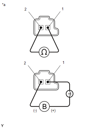
(b) Measure the resistance according to the value(s) in the table below.
Standard Resistance:
| Tester Connection | Condition | Specified Condition |
|---|---|---|
| Solenoid (SL6) valve connector terminal 1 - terminal 2 | 20°C (68°F) | 5.0 to 5.6 Ω |
(c) Connect a positive (+) lead from the battery with a 21 W bulb to terminal 1 and a negative (-) lead to terminal 2 of the solenoid valve connector. Check that the valve moves and makes an operating sound.
OK:
Valve moves and makes an operating sound.
| OK | | REPAIR OR REPLACE TRANSMISSION WIRE |
| NG | | REPLACE SOLENOID (SL6) VALVE |
READ NEXT:
 Internal Control Module EEPROM Data Memory Failure (P062F44)
DESCRIPTION The ECM monitors its internal operation and will store this DTC when it detects an internal malfunction. DTC No. Detection Item DTC Detection Condition Trouble Area MIL Memory
Torque Converter Clutch Actuator Stuck On (P07407E)
DESCRIPTION The ECM uses signals from the throttle position sensor, mass air flow meter, transmission revolution sensor (NT), transmission revolution sensor (NC) and crankshaft position sensor to help
Pressure Control Solenoid "A" Actuator Stuck Off (P07457F)
DESCRIPTION Based on signals from the transmission revolution sensors (NT and NC), the actual gear is detected. The ECM compares the actual gear with the shift schedule in the ECM memory to detect mec
SEE MORE:
Abbreviations Used In Manual
ABBREVIATIONS USED IN MANUAL
Abbreviation
Meaning
ABS
Anti-Lock Brake System
A/C
Air Conditioner
AC
Alternating Current
ACC
Accessory
ACIS
Brake
BRAKE
INSPECT BRAKE LINE PIPES AND HOSES
HINT:
Work in a well-lighted area. Turn the front wheels fully to the right or left
before beginning the inspection.
(a) Using a mirror, check the entire circumference and length of the brake lines
and hoses for:
Damage
Wear
Deformatio
