Lexus ES: Torque Converter Clutch Actuator Stuck On (P07407E)
DESCRIPTION
The ECM uses signals from the throttle position sensor, mass air flow meter, transmission revolution sensor (NT), transmission revolution sensor (NC) and crankshaft position sensor to help determine the engagement timing of the lock-up clutch. The ECM monitors the engagement of the clutch using the transmission revolution sensor (NT), transmission revolution sensor (NC) and crankshaft position sensor.
Then the ECM compares the engagement condition of the lock-up clutch with the lock-up schedule in the ECM memory to detect solenoid (SL) valve, transmission valve body assembly and torque converter assembly mechanical problems.
| DTC No. | Detection Item | DTC Detection Condition | Trouble Area | MIL | Memory | Note |
|---|---|---|---|---|---|---|
| P07407E | Torque Converter Clutch Actuator Stuck On | All of the following conditions are met (2-trip detection logic):
|
| Comes on | DTC stored | SAE Code: P0741 |
MONITOR DESCRIPTION
Torque converter lock-up is controlled by the ECM based on the transmission revolution sensor (NT), transmission revolution sensor (NC), engine speed, engine load, engine temperature, vehicle speed, automatic transaxle fluid temperature, and gear selection. The ECM determines the lock-up status of the torque converter by comparing the engine speed (NE) to the input turbine speed (NT). The ECM calculates the actual transmission gear by comparing the input turbine speed (NT) to the output shaft speed (NC). When certain conditions are met, the ECM requests "lock-up" by cutting control voltage to the solenoid (SL) valve. When the solenoid (SL) valve is turned off, pressure is applied to the lock-up relay valve and the torque converter is locked.
If the ECM detects no lock-up after lock-up has been requested or if it detects lock-up when it is not requested, the ECM interprets this as a fault in the solenoid (SL) valve or lock-up system performance. The ECM will illuminate the MIL and store the DTC.
HINT:
Example:
When any of the following is met, the system judges it as a malfunction.
-
There is a difference in rotation speed between the input side (engine speed) and output side (input turbine speed) of the torque converter when the ECM commands lock-up.
(Engine speed is at least 120 rpm more than the input turbine speed.)
-
There is no difference in rotation speed between the input side (engine speed) and output side (input turbine speed) of the torque converter when the ECM commands lock-up off.
(The difference between engine speed and input turbine speed is less than 35 rpm.)
MONITOR STRATEGY
| Related DTCs | P0741: Solenoid (SL) valve ON malfunction |
| Required sensors/components | Solenoid (SL) valve, Transmission revolution sensor (NT), Transmission revolution sensor (NC), Crankshaft position sensor (NE), Throttle position sensor (VPA1), Mass air flow meter (MAF), ATF temperature sensor (THO1), Engine coolant temperature sensor (ECT) |
| Frequency of operation | Continuous |
| Duration | ON malfunction (A): 3.5 sec. ON malfunction (B): 0.5 sec. ON malfunction (C): - |
| MIL operation | 2 driving cycles |
| Sequence of operation | None |
TYPICAL ENABLING CONDITIONS
All:| The monitor will run whenever the following DTCs are not stored | P0712, P0713 (TFT (ATF temperature) sensor circuit) P0117, P0118 (ECT (Engine coolant temperature) sensor circuit) P0717, P07BF, P07C0 (Turbine speed sensor circuit) P0793, P07C5, P07C6 (Intermediate shaft speed sensor circuit) P0962, P0963 (Solenoid (SL1) valve circuit) P0966, P0967 (Solenoid (SL2) valve circuit) P0970, P0971 (Solenoid (SL3) valve circuit) P2814, P2815 (Solenoid (SL4) valve circuit) P281D, P281E (Solenoid (SL5) valve circuit) P08C1, P08C2 (Solenoid (SL6) valve circuit) P2763, P2764 (Solenoid (SLU) valve circuit) P2720, P2721 (Solenoid (SLT) valve circuit) P2769, P2770 (Solenoid (SL) valve circuit) P0335, P0337, P0338 (Crankshaft position sensor circuit) P0327, P0328, P0332, P0333 (KCS (Knock control sensor) circuit) P0121, P0122, P0123, P0222, P0223, P0604, P0606, P060A, P060B, P060D, P060E, P061E, P0657, P0658, P2102, P2103, P2111, P2112, P2119, P2135 (ETCS (Electronic throttle control system)) U0100 (CAN communication system) |
| Shift position | "D", "not R" and "not N" |
| Elapsed time since shift lever moved from "N" to "D" | 4 sec. or more |
| TFT (ATF temperature) | -10°C (14°F) or higher |
| Engine | Running |
| Fail-safe function does not operate due to the following malfunctions: | - |
| Solenoid (SLT) valve | ON malfunction (P2714) |
| Solenoid (SLU) valve | OFF or ON malfunction (P2757) |
| Solenoid (SL) valve | ON malfunction (P0741) |
| ECT (Engine coolant temperature) | 40°C (104°F) or higher |
| Spark advance from Max. retard timing by KCS control | 0°CA or more |
| ECM selected gear | Actual gear |
| Vehicle speed | 10 km/h (6.2 mph) or more |
| ECM commanded solenoid (SL) valve state | OFF |
| ECM commanded pressure value using solenoid (SLU) valve (3 sec. or more) | - |
| - when A/C off | 515 kPa (5.3 kgf/cm2, 75 psi) or more |
| - when A/C on | 515 kPa (5.3 kgf/cm2, 75 psi) or more |
| Fail-safe function does not operate due to the following malfunctions: | - |
| Solenoid (SL1) valve | OFF or ON malfunction (P0746) |
| Solenoid (SL2) valve | OFF or ON malfunction (P0776) |
| Solenoid (SL3) valve | OFF or ON malfunction (P0796) |
| Solenoid (SL4) valve | OFF or ON malfunction (P2808) |
| Solenoid (SL5) valve | OFF or ON malfunction (P2817) |
| Solenoid (SL6) valve | OFF or ON malfunction (P08BB) |
| Solenoid (SLT) valve | OFF malfunction (P2714) |
| Solenoid (SLU) valve | ON malfunction (P2757) |
| Solenoid (SL) valve | ON malfunction (P0741) |
| All shift solenoid | Not being stopped |
| Neutral command flag | Not met |
| Vehicle stop check | Fixed |
| ECM selected gear | 3rd, 4th, 6th or 7th |
| ECM selected gear | 3rd, 4th, 6th or 7th |
HINT:
Actual gear:- 1st gear
2nd gearAny of the following conditions are met
(a) or (b)
(a) Turbine speed/Output speed (NT/NO)
4.682 or more and 9.515 or less
(When output speed less than 50 rpm)
(b) NT-NO x 1st gear ratio
-50 rpm or more and 50 rpm or less
(When output speed 50 rpm or more)
3rd gearAny of the following conditions are met
(a) or (b)
(a) Turbine speed/Output speed (NT/NO)
2.900 or more and 3.467 or less
(When output speed less than 180 rpm)
(b) NT-NO x 2nd gear ratio
-50 rpm or more and 50 rpm or less
(When output speed 180 rpm or more)
4th gearAny of the following conditions are met
(a) or (b)
(a) Turbine speed/Output speed (NT/NO)
1.910 or more and 2.189 or less
(When output speed less than 350 rpm)
(b) NT-NO x 3rd gear ratio
-50 rpm or more and 50 rpm or less
(When output speed 350 rpm or more)
5th gearAny of the following conditions are met
(a) or (b)
(a) Turbine speed/Output speed (NT/NO)
1.401 or more and 1.581 or less
(When output speed less than 350 rpm)
(b) NT-NO x 4th gear ratio
-50 rpm or more and 50 rpm or less
(When output speed 350 rpm or more)
6th gearAny of the following conditions are met
(a) or (b)
(a) Turbine speed/Output speed (NT/NO)
1.142 or more and 1.323 or less
(When output speed less than 550 rpm)
(b) NT-NO x 5th gear ratio
-50 rpm or more and 50 rpm or less
(When output speed 550 rpm or more)
7th gearAny of the following conditions are met
(a) or (b)
(a) Turbine speed/Output speed (NT/NO)
0.934 or more and 1.065 or less
(When output speed less than 750 rpm)
(b) NT-NO x 6th gear ratio
-50 rpm or more and 50 rpm or less
(When output speed 750 rpm or more)
8th gearAny of the following conditions are met
(a) or (b)
(a) Turbine speed/Output speed (NT/NO)
0.737 or more and 0.867 or less
(When output speed less than 750 rpm)
(b) NT-NO x 7th gear ratio
-50 rpm or more and 50 rpm or less
(When output speed 750 rpm or more)
Any of the following conditions are met
(a) or (b)
(a) Turbine speed/Output speed (NT/NO)
0.621 or more and 0.725 or less
(When output speed less than 950 rpm)
(b) NT-NO x 8th gear ratio
-50 rpm or more and 50 rpm or less
(When output speed 950 rpm or more)
| Engine speed | 7200 rpm or more |
| Turbine speed | 7200 rpm or more |
-
Any of the following conditions are met: Condition (a) or (b)
-
Condition (a)
ECM selected gear
6th, 7th or 8th
Output speed x 5th gear ratio
7200 rpm or more
Condition (b)
ECM selected gear
4th or 5th
Output speed x 3rd gear ratio
7200 rpm or more
-
Condition (a)
| Vehicle speed | 0 km/h (0 mph) or less |
TYPICAL MALFUNCTION THRESHOLDS
Any of the following conditions are met: ON malfunction (A), (B) or (C)
ON malfunction (A):| Engine speed - Turbine speed | 120 rpm or more |
| Neutral state flag | ON |
| Solenoid (SLT) valve | ON malfunction |
| Turbine speed - output speed x (ECM selected gear ratio) | 1000 rpm or more |
CONFIRMATION DRIVING PATTERN
CAUTION:
When performing the confirmation driving pattern, obey all speed limits and traffic laws.
HINT:
- After repairs have been completed, clear the DTCs and then check that the vehicle has returned to normal by performing the following All Readiness check procedure.
-
When clearing the permanent DTCs, refer to the Clear Permanent DTC procedure.
Click here
.gif)
- Connect the Techstream to the DLC3.
- Turn the engine switch on (IG) and turn the Techstream on.
- Clear the DTCs (even if no DTCs are stored, perform the clear DTC procedure).
- Turn the engine switch off and wait for 2 minutes or more.
- Turn the engine switch on (IG) and turn the Techstream on.
- Start the engine.
-
Perform the Lock-up Function inspection in Road Test. [*1]
Click here
HINT:
[*1] : Normal judgment procedure.
The normal judgment procedure is used to complete DTC judgment and also used when clearing permanent DTCs.
- Stop the vehicle.
- Enter the following menus: Powertrain / Transmission / Utility / All Readiness.
- Input the DTC: P07407E.
-
Check the DTC judgment result.
Techstream Display
Description
NORMAL
- DTC judgment completed
- System normal
ABNORMAL
- DTC judgment completed
- System abnormal
INCOMPLETE
- DTC judgment not completed
- Perform driving pattern after confirming DTC enabling conditions
N/A
- Unable to perform DTC judgment
- Number of DTCs which do not fulfill DTC preconditions has reached ECU memory limit
HINT:
- If the judgment result shows NORMAL, the system is normal.
- If the judgment result shows ABNORMAL, the system has a malfunction.
- If the judgment result shows INCOMPLETE or N/A, perform the normal judgment procedure again.
WIRING DIAGRAM
Refer to DTC P074011.
Click here
CAUTION / NOTICE / HINT
NOTICE:
-
Perform the universal trip to clear permanent DTCs.
Click here
-
Perform registration and/or initialization when parts related to the automatic transaxle are replaced.
Click here
ACTIVE TEST
HINT:
Using the Techstream to perform Active Tests allows relays, VSVs, actuators and other items to be operated without removing any parts. This non-intrusive functional inspection can be very useful because intermittent operation may be discovered before parts or wiring is disturbed. Performing Active Tests early in troubleshooting is one way to save diagnostic time. Data List information can be displayed while performing Active Tests.
(a) Warm up the engine.
(b) Turn the engine switch off.
(c) Connect the Techstream to the DLC3.
(d) Turn the engine switch on (IG).
(e) Turn the Techstream on.
(f) Enter the following menus: Powertrain / Transmission / Active Test.
(g) According to the display on the Techstream, perform the Active Test.
Powertrain > Transmission > Active Test| Tester Display | Measurement Item | Control Range | Diagnostic Note |
|---|---|---|---|
| Activate the Lock Up Solenoid | Operates the solenoid (SLU and SL) valve to control the automatic transaxle lock-up condition | ON or OFF | Can be used to check the operation of the solenoid (SLU and SL) valve. [Vehicle Condition] Vehicle speed: 60 km/h (36 mph) or more |
| Tester Display |
|---|
| Activate the Lock Up Solenoid |
HINT:
This test can be conducted when the vehicle speed is 60 km/h (36 mph) or more.
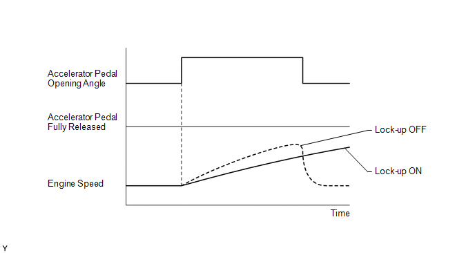
(h) Lightly depress the accelerator pedal and check that the engine speed does not change abruptly.
HINT:
- When changing the accelerator pedal opening angle while driving, if the engine speed does not change, lock-up is on.
- Slowly release the accelerator pedal in order to decelerate, but do not fully release the pedal. (Fully releasing the pedal will close the throttle valve and lock-up may be prohibited.)
PROCEDURE
| 1. | CHECK OTHER DTCS OUTPUT (IN ADDITION TO DTC P07407E) |
(a) Connect the Techstream to the DLC3.
(b) Turn the engine switch on (IG).
(c) Turn the Techstream on.
(d) Enter the following menus: Powertrain / Transmission / Trouble Codes.
Powertrain > Transmission > Trouble Codes(e) Read the DTCs using the Techstream.
| Result | Proceed to |
|---|---|
| Only DTC P07407E is output | A |
| DTC P07407E and other DTCs are output | B |
HINT:
If any other codes besides P07407E are output, perform the troubleshooting for those DTCs first.
| B | .gif) | GO TO DTC CHART |
|
.gif)
| 2. | INSPECT TRANSMISSION WIRE (SOLENOID (SL) VALVE) |
| (a) Disconnect the C30 transmission wire connector. |
|
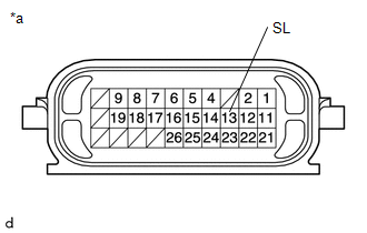
(b) Measure the resistance according to the value(s) in the table below.
Standard Resistance:
| Tester Connection | Condition | Specified Condition |
|---|---|---|
| 13 (SL) - Body ground | 20°C (68°F) | 11 to 15 Ω |
| NG | | GO TO STEP 7 |
|
| 3. | INSPECT SOLENOID (SL) VALVE (OPERATION) |
| (a) Remove the solenoid (SL) valve. Click here |
|
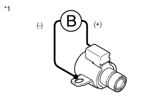
(b) Connect a positive (+) lead from the battery to the terminal of the solenoid valve connector, and a negative (-) lead to the solenoid body. Check that the valve moves and makes an operating sound.
OK:
Valve moves and makes an operating sound.
| NG | | REPLACE SOLENOID (SL) VALVE |
|
| 4. | INSPECT TRANSMISSION VALVE BODY ASSEMBLY |
(a) Inspect the transmission valve body assembly.
Click here
OK:
There is no foreign matter on each valve and they operate smoothly.
| NG | | REPAIR OR REPLACE TRANSMISSION VALVE BODY ASSEMBLY |
|
| 5. | INSPECT TORQUE CONVERTER ASSEMBLY |
(a) Inspect the torque converter assembly.
Click here
OK:
The torque converter assembly is normal.
| NG | | REPAIR OR REPLACE TORQUE CONVERTER ASSEMBLY |
|
| 6. | REPAIR OR REPLACE AUTOMATIC TRANSAXLE ASSEMBLY |
(a) Repair or replace the automatic transaxle assembly.
Click here
| NEXT | | PERFORM REGISTRATION |
| 7. | INSPECT SOLENOID (SL) VALVE (RESISTANCE) |
| (a) Remove the solenoid (SL) valve. Click here |
|
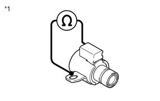
(b) Measure the resistance according to the value(s) in the table below.
Standard Resistance:
| Tester Connection | Condition | Specified Condition |
|---|---|---|
| Solenoid (SL) valve connector terminal - Solenoid (SL) valve body | 20°C (68°F) | 11 to 15 Ω |
| OK | | REPAIR OR REPLACE TRANSMISSION WIRE |
| NG | | REPLACE SOLENOID (SL) VALVE |
READ NEXT:
 Pressure Control Solenoid "A" Actuator Stuck Off (P07457F)
DESCRIPTION Based on signals from the transmission revolution sensors (NT and NC), the actual gear is detected. The ECM compares the actual gear with the shift schedule in the ECM memory to detect mec
Pressure Control Solenoid "B" Actuator Stuck Off (P07757F)
DESCRIPTION Based on signals from the transmission revolution sensors (NT and NC), the actual gear is detected. The ECM compares the actual gear with the shift schedule in the ECM memory to detect mec
Pressure Control Solenoid "C" Actuator Stuck Off (P07957F)
DESCRIPTION Based on signals from the transmission revolution sensors (NT and NC), the actual gear is detected. The ECM compares the actual gear with the shift schedule in the ECM memory to detect mec
SEE MORE:
Installation
INSTALLATION CAUTION / NOTICE / HINT HINT:
Use the same procedure for the RH side and LH side.
The following procedure is for the LH side.
PROCEDURE 1. TEMPORARILY INSTALL REAR NO. 1 SUSPENSION ARM ASSEMBLY (a) Temporarily install the rear No. 1 suspension arm assembly to the rear axle carri
Diagnostic Trouble Code Chart
DIAGNOSTIC TROUBLE CODE CHART Power Trunk Lid System DTC No. Detection Item Link B2205 Kick Sensor Circuit B2222 PBD/PTL Pulse Sensor B2225 PBD/PTL Motor Clutch Malfunction B2250 PBD/PTL Closer Operation B2251 PBD/PTL Closer Switch U0
