Lexus ES: Power Window Master Switch
Components
COMPONENTS
ILLUSTRATION
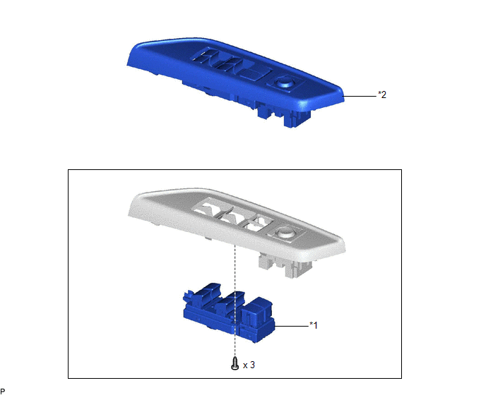
| *1 | MULTIPLEX NETWORK MASTER SWITCH ASSEMBLY | *2 | MULTIPLEX NETWORK MASTER SWITCH ASSEMBLY WITH FRONT DOOR UPPER ARMREST BASE PANEL |
Removal
REMOVAL
PROCEDURE
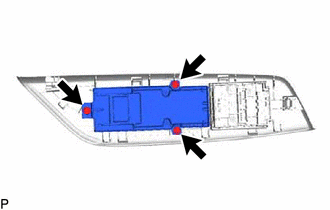
1. REMOVE MULTIPLEX NETWORK MASTER SWITCH ASSEMBLY WITH FRONT DOOR UPPER ARMREST BASE PANEL
Click here .gif)
2. REMOVE MULTIPLEX NETWORK MASTER SWITCH ASSEMBLY
| (a) Remove the 3 screws and multiplex network master switch assembly. |
|
Inspection
INSPECTION
PROCEDURE
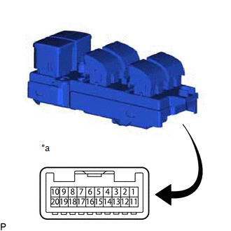
1. INSPECT MULTIPLEX NETWORK MASTER SWITCH ASSEMBLY
| (a) Check that the LEDs illuminate. (1) Apply auxiliary battery voltage to the multiplex network master switch assembly and check that the LEDs illuminate. OK:
If the result is not as specified, replace the multiplex network master switch assembly. |
|
READ NEXT:
 Components
COMPONENTS ILLUSTRATION *A for Driver Side *B for Front Passenger Side *1 COURTESY LIGHT ASSEMBLY *2 FRONT DOOR TRIM BOARD SUB-ASSEMBLY *3 MULTIPLEX NETWORK MASTER SWITCH ASS
Removal
REMOVAL CAUTION / NOTICE / HINT The necessary procedures (adjustment, calibration, initialization, or registration) that must be performed after parts are removed and installed, or replaced during pow
SEE MORE:
The Display of the Multi-display does not Switched
DESCRIPTION The multi-display receives a signal from the clearance warning ECU assembly to change the display screen. WIRING DIAGRAM PROCEDURE 1. CHECK HARNESS AND CONNECTOR (CLEARANCE WARNING ECU ASSEMBLY - MULTI-DISPLAY ASSEMBLY) (a) Disconnect the N41 clearance warning ECU assembly conn
Absorber Control Actuator(for Rear Side)
On-vehicle InspectionON-VEHICLE INSPECTION PROCEDURE 1. INSPECT ABSORBER CONTROL ACTUATOR (a) Measure the resistance according to the value(s) in the table below. Standard Resistance: Tester Connection Condition Specified Condition 1 - 3 15 to 25°C 3.3 to 3.7 Ω If the result
