Lexus ES: The Display of the Multi-display does not Switched
DESCRIPTION
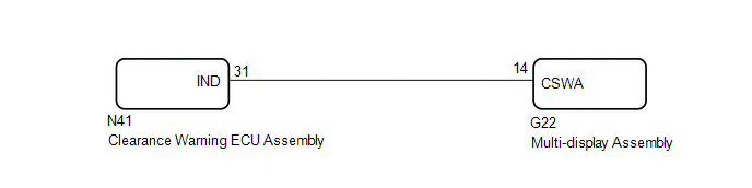
The multi-display receives a signal from the clearance warning ECU assembly to change the display screen.
WIRING DIAGRAM
PROCEDURE
| 1. | CHECK HARNESS AND CONNECTOR (CLEARANCE WARNING ECU ASSEMBLY - MULTI-DISPLAY ASSEMBLY) |
(a) Disconnect the N41 clearance warning ECU assembly connector.
(b) Disconnect the G22 multi-display assembly connector.
(c) Measure the resistance according to the value(s) in the table below.
Standard Resistance:
| Tester Connection | Condition | Specified Condition |
|---|---|---|
| N41-31 (IND) - G22-14 (CSWA) | Always | Below 1 Ω |
| N41-31 (IND) or G22-14 (CSWA) - Body ground | Always | 10 kΩ or higher |
| NG |  | REPAIR OR REPLACE HARNESS OR CONNECTOR |
|

| 2. | INSPECT CLEARANCE WARNING ECU ASSEMBLY |
| (a) Connect the N41 clearance warning ECU assembly connector. |
|
.png)
(b) Measure the voltage according to the value(s) in the table below.
Standard Voltage:
| Tester Connection | Condition | Specified Condition |
|---|---|---|
| N41-31 (IND) - Body ground | Power switch on (IG) Shift lever in any position other than P | Below 3 V |
| N41-31 (IND) - Body ground | Power switch on (IG) Shift lever in P | 8 V or higher |
| OK | | PROCEED TO NEXT SUSPECTED AREA SHOWN IN PROBLEM SYMPTOMS TABLE |
| NG | | REPLACE CLEARANCE WARNING ECU ASSEMBLY |
READ NEXT:
 Control Module Communication Bus "A" Off (U0073,U0126,U0129,U0140,U0155)
DESCRIPTION These DTCs are stored when the clearance warning ECU assembly cannot receive and recognize several signals via the CAN communication line. DTC No. Detection Item DTC Detection Condi
CAN Communication Failure (Message Registry) (U1000)
DESCRIPTION If DTC U1000 is stored frequently, duplicate the conditions that cause the problem symptoms and perform troubleshooting again even if the DTC is not output when rechecking for DTCs. DTC
SEE MORE:
Windshield Deicer does not Operate
DESCRIPTION When the front wiper deicer switch is operated, the operation signal is transmitted to the air conditioning amplifier assembly directly. When the air conditioning amplifier assembly receives the signal, it turns on the DEICER relay to operate the windshield deicer system. WIRING DIAGRAM
Installation
INSTALLATION PROCEDURE 1. INSTALL NO. 2 CYLINDER HEAD GASKET (a) Place a new No. 2 cylinder head gasket on the cylinder block sub-assembly as shown in the illustration. *a Lot No. Front of Engine NOTICE:
Remove any oil from the contact surfaces.
Make sure to install the No. 2 cy
