Lexus ES: PBD/PTL Closer Switch (B2251)
DESCRIPTION
DTC B2251 is output if there is a malfunction in the half latch switch circuit of the luggage door closer assembly.
| DTC No. | Detection Item | DTC Detection Condition | Trouble Area |
|---|---|---|---|
| B2251 | PBD/PTL Closer Switch | When luggage door is opening or closing, malfunction occurs in half latch switch or pawl switch circuit of luggage door closer assembly. |
|
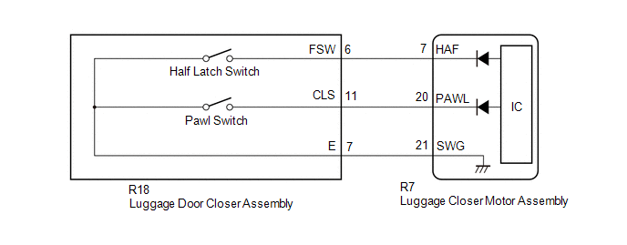
WIRING DIAGRAM
CAUTION / NOTICE / HINT
NOTICE:
- If a luggage closer motor assembly DTC is output, the luggage compartment door closer operation and power trunk lid operation is stops.
-
If the luggage closer motor assembly has been removed and installed or replaced, or if any of the connectors has been disconnected, initialize the power trunk lid system.
Click here
.gif)
PROCEDURE
| 1. | CHECK FOR DTC |
(a) Connect the Techstream to the DLC3.
(b) Turn the engine switch on (IG)
(c) Turn the Techstream on.
(d) Enter the following menus: Body Electrical / Back Door / Trouble Codes.
(e) Clear the DTCs.
Body Electrical > Back Door > Clear DTCs(f) Check for DTCs.
Body Electrical > Back Door > Trouble CodesOK:
DTC B2251 is not output.
| OK | .gif) | USE SIMULATION METHOD TO CHECK |
|
.gif)
| 2. | READ VALUE USING TECHSTREAM |
(a) Enter the following menus: Body Electrical / Back Door / Data List.
(b) Read the Data List according to the display on the Techstream.
Click here
| Tester Display | Measurement Item | Range | Normal Condition | Diagnostic Note |
|---|---|---|---|---|
| Half Latch SW | Luggage door closer assembly (half latch switch) signal | OFF or ON | ON: Luggage door closer assembly open-latched OFF: Luggage door closer assembly full-latched or half-latched | - |
| Pawl Position Switch | Luggage door closer assembly (pawl switch) signal | OFF or ON | ON: Luggage door closer assembly half-latched OFF: Luggage door closer assembly except half -latched | - |
| Tester Display |
|---|
| Half Latch SW |
OK:
The Data List display changes according to luggage compartment door operation.
| OK | | REPLACE LUGGAGE CLOSER MOTOR ASSEMBLY |
|
| 3. | INSPECT LUGGAGE DOOR CLOSER ASSEMBLY |
(a) Remove the luggage door closer assembly.
Click here
(b) Inspect the luggage door closer assembly. (each switchs)
Click here
| NG | | REPLACE LUGGAGE DOOR CLOSER ASSEMBLY |
|
| 4. | CHECK HARNESS AND CONNECTOR (LUGGAGE CLOSER MOTOR ASSEMBLY - LUGGAGE DOOR CLOSER ASSEMBLY) |
(a) Disconnect the R7 luggage closer motor assembly connector.
(b) Measure the resistance according to the value(s) in the table below.
Standard Resistance:
| Tester Connection | Condition | Specified Condition |
|---|---|---|
| R7-7 (HAF) - R18-6 (FSW) | Always | Below 1 Ω |
| R7-20 (PAWL) - R18-11 (CLS) | Always | Below 1 Ω |
| R7-7 (HAF) or R18-6 (FSW) - Body ground | Always | 10 kΩ or higher |
| R7-20 (PAWL) or R18-11 (CLS) - Body ground | Always | 10 kΩ or higher |
| OK | | REPLACE LUGGAGE CLOSER MOTOR ASSEMBLY |
| NG | | REPAIR OR REPLACE HARNESS OR CONNECTOR |
READ NEXT:
 Lost Communication with TCM (U0101,U0122,U0142,U0155,U0327,U1117)
DESCRIPTION DTC No. Detection Item DTC Detection Condition Trouble Area U0101 Lost Communication with TCM Communication malfunction detected between luggage closer motor assembly and
Luggage Compartment Door Closer does not Operate
DESCRIPTION The luggage compartment door closer operation controls the luggage door closer assembly via the luggage closer motor assembly based on switch signals in the luggage door closer assembly. W
Power Trunk Lid does not Operate Using Any Switches
DESCRIPTION The power trunk lid controls the luggage closer motor assembly and operates the luggage closer motor assembly and luggage door closer assembly. If the power trunk lid does not operate usin
SEE MORE:
Front Side Marker Light Bulb
Components
COMPONENTS
ILLUSTRATION
*1
FRONT SIDE MARKER LIGHT BULB
*2
REAR FENDER SPLASH SHIELD SUB-ASSEMBLY
*3
FRONT FENDER LINER RETAINER
*4
PIN HOLD CLIP
Removal
REMOVAL
CAUTION / NO
Freeze Frame Data
FREEZE FRAME DATA CHECK FREEZE FRAME DATA HINT: Whenever an active noise control system DTC is stored, the stereo component equalizer assembly stores the current vehicle state as freeze frame data. (a) Connect the Techstream to the DLC3. (b) Turn the engine switch on (IG). (c) Turn the Techstream on
