Lexus ES: Front Side Marker Light Bulb
Components
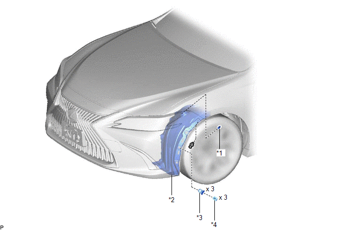
COMPONENTS
ILLUSTRATION
|
*1 |
FRONT SIDE MARKER LIGHT BULB |
*2 |
REAR FENDER SPLASH SHIELD SUB-ASSEMBLY |
|
*3 |
FRONT FENDER LINER RETAINER |
*4 |
PIN HOLD CLIP |
Removal
REMOVAL
CAUTION / NOTICE / HINT
HINT:
- Use the same procedure for the RH side and LH side.
- The following procedure is for the LH side.
PROCEDURE
1. SEPARATE REAR FENDER SPLASH SHIELD SUB-ASSEMBLY
Click here .gif)
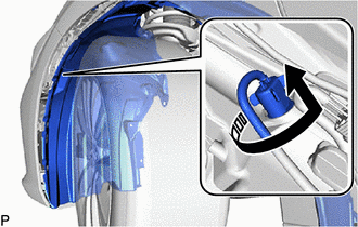
2. REMOVE FRONT SIDE MARKER LIGHT BULB
(a) Turn the headlight cord with the front side marker light bulb as shown in the illustration to disconnect them as a unit.
.png) |
Disconnect in this Direction |
(b) Remove the front side marker light bulb from the headlight cord.
Installation
INSTALLATION
CAUTION / NOTICE / HINT
HINT:
- Use the same procedure for the RH side and LH side.
- The following procedure is for the LH side.
PROCEDURE
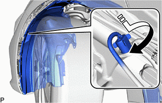
1. INSTALL FRONT SIDE MARKER LIGHT BULB
(a) Install the front side marker light bulb to the headlight cord.
(b) Turn the headlight cord with the front side marker light bulb as shown in the illustration to install them as a unit.
.png) |
Install in this Direction |
2. INSTALL REAR FENDER SPLASH SHIELD SUB-ASSEMBLY
Click here .gif)
READ NEXT:
 Front Turn Signal Light Bulb
Components
COMPONENTS
ILLUSTRATION
*1
FRONT TURN SIGNAL LIGHT BULB
*2
REAR FENDER SPLASH SHIELD SUB-ASSEMBLY
*3
FRONT FEN
Front Wiper Rubber
Components
COMPONENTS
ILLUSTRATION
*1
FRONT WIPER BLADE
*2
WIPER RUBBER
*3
FRONT WIPER RUBBER BACKING PLATE
-
SEE MORE:
Fuel Pump Control (All Phase) Circuit Open (P12D013-P12D313)
DESCRIPTION Refer to DTC P062712. Click here DTC No. Detection Item DTC Detection Condition Trouble Area MIL Memory Note P12D013 Fuel Pump Control (All Phase) Circuit Open When the fuel pump control ECU operation duty ratio is 3 to 65%, an open is detected in the FPU, FPV an
Removal
REMOVAL CAUTION / NOTICE / HINT The necessary procedures (adjustment, calibration, initialization or registration) that must be performed after parts are removed and installed, or replaced during PCV valve (ventilation valve sub-assembly) removal/installation are shown below. Necessary Procedures Af
