Lexus ES: Drive Start Control
DESCRIPTION
The drive start control is controlled by the hybrid vehicle control ECU.
If the hybrid vehicle control ECU determines that the shift lever and accelerator pedal are operated abnormally, hybrid system output is restricted and, when necessary, a warning is displayed on the combination meter assembly.

CAUTION / NOTICE / HINT
HINT:
Even if the accelerator pedal position is maintained, the hybrid system output may increase when driving uphill and decrease when driving downhill. This is due to drive start control controlling the hybrid system output, and is not a malfunction.
PROCEDURE
| 1. | SYMPTOM CONFIRMATION |
(a) Interview the customer to confirm the problem.
| Result | Proceed to |
|---|---|
| Hunting | A |
| Hesitation/poor acceleration | B |
| B | .gif) | GO TO STEP 8 |
|
.gif)
| 2. | PAST ACTIVATION CONFIRMATION |
(a) Check if the customer operated the vehicle in a way that would cause the drive start control to operate.
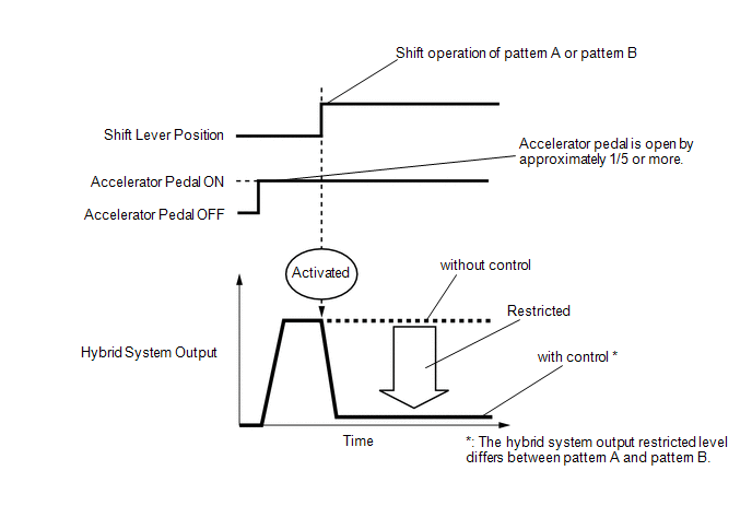
Drive Start Control Activation Conditions- Activation conditions
-
Pattern A (When all of the following conditions are met, control starts.)
- The accelerator pedal is open by approximately 1/5 or more.
- The shift lever is moved from P to (D or S) or R.
-
Pattern B (When all of the following conditions are met, control starts.)
- The accelerator pedal is open by approximately 1/5 or more.
-
The shift lever is moved from R to (D or S), from (D or S) or N to R.
-
Items Controlled
- Hybrid system output is restricted.
-
Deactivation Conditions
- The accelerator pedal is released.
- The shift lever is in P or N.
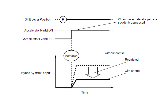
- Activation conditions
- The shift lever is in R.
-
The accelerator pedal is depressed excessively.
-
Items Controlled
- Hybrid system output is restricted.
-
Deactivation Conditions
- The accelerator pedal is released.
- The shift lever is moved to any position other than R.
HINT:
- The hybrid system output restricted level differs between Pattern A, Pattern B and Reverse control.
- During Shift control or Reverse control, hybrid system output is adjusted based on the road gradient and steering angle.
| Result | Proceed to |
|---|---|
| Performed | A |
| Not performed | B |
| B | | SYSTEM NORMAL (GO TO PROBLEM SYMPTOM TABLE) |
|
| 3. | CHECK DTC OUTPUT (HEALTH CHECK) |
(a) Connect the Techstream to the DLC3.
(b) Turn the power switch on (IG).
(c) Turn the Techstream on.
(d) Enter the following menus: System Select / Health Check.
(e) Check the DTCs.
(f) Turn the power switch off.
| Result | Proceed to |
|---|---|
| DTCs are not output | A |
| DTC is output | B |
| B | | GO TO DTC CHART |
|
| 4. | READ VALUE USING TECHSTREAM (FR, FL, RR, RL WHEEL SPEED) |
(a) Connect the Techstream to the DLC3.
(b) Turn the power switch on (READY).
(c) Turn the Techstream on.
(d) Enter the following menus: Chassis / ABS/VSC/TRAC / Data List / FR Wheel Speed, FL Wheel Speed, RR Wheel Speed and RL Wheel Speed.
Chassis > ABS/VSC/TRAC > Data List| Tester Display |
|---|
| FR Wheel Speed |
| FL Wheel Speed |
| RR Wheel Speed |
| RL Wheel Speed |
(e) Read the values displayed on the Techstream.
Standard:
| Condition | Specified Condition |
|---|---|
| Vehicle stopped | 0 km/h (0 mph) |
| Vehicle being driven at constant speed between 16 to 64 km/h (10 to 40 mph) | No large fluctuations when driving at a constant speed |
CAUTION:
When performing the confirmation driving pattern, obey all speed limits and traffic laws.
HINT:
Data can be captured relatively easily by using the snapshot function in the Data List. Confirm the data after performing the drive test.
(f) Turn the power switch off.
| NG | | INSPECT FRONT OR REAR SPEED SENSOR |
|
| 5. | READ VALUE USING TECHSTREAM (VEHICLE SPEED) |
(a) Connect the Techstream to the DLC3.
(b) Turn the power switch on (READY).
(c) Turn the Techstream on.
(d) Enter the following menus: Powertrain / Hybrid Control / Data List / Vehicle Speed.
Powertrain > Hybrid Control > Data List| Tester Display |
|---|
| Vehicle Speed |
(e) Read the value displayed on the Techstream.
Standard:
| Inspection Condition | Specified Condition |
|---|---|
| Vehicle stopped | 0 km/h (0 mph) |
| Vehicle being driven at a constant speed (16 to 64 km/h (10 to 40 mph)) | No large fluctuations in displayed speed |
CAUTION:
Perform this road test only in an appropriate safe location, in accordance with all local laws.
HINT:
Data can be captured relatively easily by using the snapshot function in the Data List. Confirm the data after performing the drive test.
(f) Turn the power switch off.
| NG | | INSPECT ELECTRONICALLY CONTROLLED BRAKE SYSTEM (HOW TO PROCEED WITH TROUBLESHOOTING) |
|
| 6. | READ VALUE USING TECHSTREAM (DECELERATION SENSOR) |
(a) Connect the Techstream to the DLC3.
(b) Turn the power switch on (READY).
(c) Turn the Techstream on.
(d) Enter the following menus: Chassis / ABS/VSC/TRAC / Data List / Deceleration Sensor, Deceleration Sensor2.
Chassis > ABS/VSC/TRAC > Data List| Tester Display |
|---|
| Deceleration Sensor |
| Deceleration Sensor2 |
(e) Read the values displayed on the Techstream.
Standard:
| Condition | Specified Condition |
|---|---|
| During deceleration | Values change with vehicle speed |
CAUTION:
When performing the confirmation driving pattern, obey all speed limits and traffic laws.
HINT:
Data can be captured relatively easily by using the snapshot function in the Data List. Confirm the data after performing the drive test.
(f) Turn the power switch off.
| NG | | INSPECT AIR BAG ECU ASSEMBLY (YAW RATE SENSOR) |
|
| 7. | READ VALUE USING TECHSTREAM (STEERING ANGLE SENSOR) |
(a) Connect the Techstream to the DLC3.
(b) Turn the power switch on (READY).
(c) Turn the Techstream on.
(d) Enter the following menus: Chassis / ABS/VSC/TRAC / Data List / Steering Angle Sensor.
Chassis > ABS/VSC/TRAC > Data List| Tester Display |
|---|
| Steering Angle Sensor |
(e) Read the value displayed on the Techstream.
Standard:
| Condition | Specified Condition |
|---|---|
| Steering wheel turned left | Value increases with steering wheel operation |
| Steering wheel turned right | Value decreases with steering wheel operation |
CAUTION:
When performing the confirmation driving pattern, obey all speed limits and traffic laws.
HINT:
Data can be captured relatively easily by using the snapshot function in the Data List. Confirm the data after performing the drive test.
(f) Turn the power switch off.
| OK | | SYSTEM NORMAL (GO TO PROBLEM SYMPTOM TABLE) |
| NG | | INSPECT STEERING ANGLE SENSOR |
| 8. | PAST ACTIVATION CONFIRMATION |
(a) Check if the customer operated the vehicle in a way that would cause the drive start control to operate.
Drive Start Control Activation Conditions- Activation conditions
-
Pattern A (When all of the following conditions are met, control starts.)
- The accelerator pedal is open by approximately 1/5 or more.
- The shift lever is moved from P to (D or S) or R.
-
Pattern B (When all of the following conditions are met, control starts.)
- The accelerator pedal is open by approximately 1/5 or more.
-
The shift lever is moved from R to (D or S), from (D or S) or N to R.
-
Items Controlled
- Hybrid system output is restricted.
-
Deactivation Conditions
- The accelerator pedal is released.
- The shift lever is in P or N.
- Activation conditions
- The shift lever is in R.
-
The accelerator pedal is depressed excessively.
-
Items Controlled
- Hybrid system output is restricted.
-
Deactivation Conditions
- The accelerator pedal is released.
- The shift lever is moved to any position other than R.
HINT:
- The hybrid system output restricted level differs between Pattern A, Pattern B and Reverse control.
- During Shift control or Reverse control, hybrid system output is adjusted based on the road gradient and steering angle.
| Result | Proceed to |
|---|---|
| Not performed | A |
| Performed | B |
HINT:
If the customer operated the vehicle in a way which caused the drive start control to operate, explain the operation of the system to the customer and that the operation is not a malfunction.
| B | | SYSTEM NORMAL |
|
| 9. | CHECK DTC OUTPUT (HEALTH CHECK) |
(a) Connect the Techstream to the DLC3.
(b) Turn the power switch on (IG).
(c) Turn the Techstream on.
(d) Enter the following menus: System Select / Health Check.
(e) Check the DTCs.
| Result | Proceed to |
|---|---|
| DTCs are not output | A |
| DTC is output | B |
(f) Turn the power switch off.
| B | | GO TO DTC CHART |
|
| 10. | INSPECT SHIFT LEVER POSITION SENSOR |
(a) Inspect the shift lever position sensor.
Click here .gif)
| Result | Proceed to |
|---|---|
| Normal | A |
| Abnormal | B |
| B | | REPLACE SHIFT LEVER POSITION SENSOR |
|
| 11. | READ VALUE USING TECHSTREAM (ACCELERATOR POSITION SENSOR NO. 1 VOLTAGE %, ACCELERATOR POSITION SENSOR NO. 2 VOLTAGE %) |
Click here
| OK | | SYSTEM NORMAL (GO TO PROBLEM SYMPTOM TABLE) |
| NG | | REPLACE ACCELERATOR PEDAL SENSOR ASSEMBLY |
READ NEXT:
 ECU Power Source Circuit
DESCRIPTION If the power switch is on (IG), the hybrid vehicle control ECU applies current to the MREL terminal to turn the IGCT relay on. This supplies power to the +B1 and +B2 terminals. WIRING DIAG
Motor Resolver Circuit
DESCRIPTION The cause of this malfunction may be the motor resolver. Check the motor resolver internal resistance and the connection condition from the inverter to the resolver. Related Parts Check
Motor High-voltage Circuit
DESCRIPTION The cause of the malfunction may be the high-voltage circuit of the motor. Check the motor internal resistance and the connection condition of the high-voltage line between the inverter an
SEE MORE:
How To Proceed With Troubleshooting
CAUTION / NOTICE / HINT HINT:
Use the following procedure to troubleshoot the power window control system.
*: Use the Techstream.
PROCEDURE 1. VEHICLE BROUGHT TO WORKSHOP
NEXT 2. CUSTOMER PROBLEM ANALYSIS HINT:
In troubleshooting, confirm that the proble
System Description
SYSTEM DESCRIPTION POWER MIRROR CONTROL SYSTEM (w/o Memory) DESCRIPTION (a) This system has the following functions: electrical remote control mirror function, power retract mirror function, mirror heater function and automatic glare-resistant EC mirror function. FUNCTION OF MAIN COMPONENT Compon
