Lexus ES: Pattern Select Switch Sport Mode Circuit
DESCRIPTION
When selecting sport mode, the switch operation signal is sent to the hybrid vehicle control ECU. Following this, the system enters sport mode and the vehicle will be driven using sport mode. This signal is then transmitted from the hybrid vehicle control ECU via CAN to the combination meter assembly to illuminate the "Sport" indicator.
WIRING DIAGRAM

PROCEDURE
| 1. | READ VALUE USING TECHSTREAM (CAN BUS CHECK) |
Click here .gif)
| Result | Proceed to |
|---|---|
| All of the ECUs and sensors that are currently connected to the CAN communication system are displayed | A |
| None of the ECUs and sensors that are currently connected to the CAN communication system are displayed, or some of them are not displayed | B |
| B | .gif) | GO TO CAN COMMUNICATION SYSTEM |
|
.gif)
| 2. | CHECK DTC OUTPUT (HEALTH CHECK) |
Click here
| Result | Proceed to |
|---|---|
| No DTCs are output | A |
| DTCs are output | B |
| B | | GO TO DTC CHART |
|
| 3. | READ VALUE USING TECHSTREAM (SPORT MODE SWITCH, NORMAL MODE SWITCH) |
(a) Connect the Techstream to the DLC3.
(b) Turn the power switch on (IG).
(c) Enter the following menus: Powertrain / Hybrid Control / Data List / Sport Mode Switch, Normal Mode Switch.
Powertrain > Hybrid Control > Data List| Tester Display |
|---|
| Sport Mode Switch |
| Normal Mode Switch |
(d) Read the value displayed on the Techstream.
| Result | Proceed to |
|---|---|
| The Techstream display changes according to the drive mode select switch (combination switch assembly) operation | A |
| The Techstream display does not change according to the drive mode select switch (combination switch assembly) operation | B |
(e) Turn the power switch off.
| A | | GO TO PROBLEM SYMPTOMS TABLES |
|
| 4. | INSPECT DRIVE MODE SELECT SWITCH (COMBINATION SWITCH ASSEMBLY) (SPORT MODE, NORMAL MODE) |
Click here
| NG | | REPLACE DRIVE MODE SELECT SWITCH (COMBINATION SWITCH ASSEMBLY) |
|
| 5. | CHECK HARNESS AND CONNECTOR (DRIVE MODE SELECT SWITCH (COMBINATION SWITCH ASSEMBLY) - BODY GROUND) |
(a) Disconnect the H12 drive mode select switch (combination switch assembly) connector.
| (b) Measure the resistance according to the value(s) in the table below. Standard Resistance:
|
|

(c) Reconnect the H12 drive mode select switch (combination switch assembly) connector.
| NG | | REPAIR OR REPLACE HARNESS OR CONNECTOR |
|
| 6. | CHECK HARNESS AND CONNECTOR (HYBRID VEHICLE CONTROL ECU - DRIVE MODE SELECT SWITCH (COMBINATION SWITCH ASSEMBLY)) |
(a) Disconnect the G59 and G60 hybrid vehicle control ECU connectors.
(b) Disconnect the H12 drive mode select switch (combination switch assembly) connector.
(c) Measure the resistance according to the value(s) in the table below.
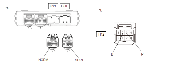
| *a | Rear view of wire harness connector (to Hybrid Vehicle Control ECU) | *b | Front view of wire harness connector (to Drive Mode Select Switch (Combination Switch Assembly)) |
Standard Resistance:
| Tester Connection | Condition | Specified Condition |
|---|---|---|
| G60-6 (SPRT) - H12-3 (P) | Always | Below 1 Ω |
| G60-6 (SPRT) or H12-3 (P) - Body ground | Always | 10 kΩ or higher |
| G59-10 (NORM) - H12-2 (B) | Always | Below 1 Ω |
| G59-10 (NORM) or H12-2 (B) - Body ground | Always | 10 kΩ or higher |
(d) Reconnect the H12 drive mode select switch (combination switch assembly) connector.
(e) Reconnect the G59 and G60 hybrid vehicle control ECU connectors.
| OK | | REPLACE HYBRID VEHICLE CONTROL ECU |
| NG | | REPAIR OR REPLACE HARNESS OR CONNECTOR |
READ NEXT:
 Pattern Select Switch Eco Mode Circuit
DESCRIPTION When selecting Eco drive mode, the drive mode select switch (combination switch assembly) (Eco drive mode) operation signal is sent to the air conditioning amplifier assembly. Following th
Indicator Circuit
DESCRIPTION In accordance with the shift lever position, each shift position indicator light will turn on. WIRING DIAGRAM PROCEDURE 1. CHECK SHIFT POSITION INDICATOR (a) Turn the power switc
ECU Power Source Circuit
DESCRIPTION If the power switch is on (IG), the hybrid vehicle control ECU applies current to the MREL terminal to turn the IGCT relay on. This supplies power to the +B1 and +B2 terminals. WIRING DIAG
SEE MORE:
Pressure Control Solenoid "A" Actuator Stuck Off (P07457F)
DESCRIPTION Based on signals from the transmission revolution sensors (NT and NC), the actual gear is detected. The ECM compares the actual gear with the shift schedule in the ECM memory to detect mechanical malfunctions of the solenoid valves, transmission valve body assembly and automatic transaxl
Motor Control Relay Stuck ON (Fr Shade) (B234A)
DESCRIPTION This DTC will be stored if the operation of the front roof sunshade is suspended and a pulse input of 10 Hz or more is detected when the motor relay is off. DTC No. Detection Item DTC Detection Condition Trouble Area B234A Motor Control Relay Stuck ON (Fr Shade) Position
