Lexus ES: Pattern Select Switch Eco Mode Circuit
DESCRIPTION
When selecting Eco drive mode, the drive mode select switch (combination switch assembly) (Eco drive mode) operation signal is sent to the air conditioning amplifier assembly. Following this, Eco drive mode control is activated for the heater and air conditioning system and the hybrid vehicle control system.
WIRING DIAGRAM

PROCEDURE
| 1. | READ VALUE USING TECHSTREAM (CAN BUS CHECK) |
Click here .gif)
| Result | Proceed to |
|---|---|
| All of the ECUs and sensors that are currently connected to the CAN communication system are displayed | A |
| None of the ECUs and sensors that are currently connected to the CAN communication system are displayed, or some of them are not displayed | B |
| B | .gif) | GO TO CAN COMMUNICATION SYSTEM |
|
.gif)
| 2. | CHECK DTC OUTPUT (HEALTH CHECK) |
Click here
| Result | Proceed to |
|---|---|
| No DTCs are output | A |
| DTCs are output | B |
| B | | GO TO DTC CHART |
|
| 3. | READ VALUE USING TECHSTREAM (ECO SWITCH) |
(a) Connect the Techstream to the DLC3.
(b) Turn the power switch on (IG).
(c) Enter the following menus: Body Electrical / Air Conditioner / Data List / ECO Switch.
Body Electrical > Air Conditioner > Data List| Tester Display |
|---|
| ECO Switch |
(d) Read the value displayed on the Techstream.
| Result | Proceed to |
|---|---|
| The Techstream display changes according to the drive mode select switch (combination switch assembly) operation | A |
| The Techstream display does not change according to the drive mode select switch (combination switch assembly) operation | B |
| A | | CHECK FOR INTERMITTENT PROBLEMS |
|
| 4. | INSPECT DRIVE MODE SELECT SWITCH (COMBINATION SWITCH ASSEMBLY) (ECO DRIVE MODE) |
Click here
| NG | | REPLACE DRIVE MODE SELECT SWITCH (COMBINATION SWITCH ASSEMBLY) |
|
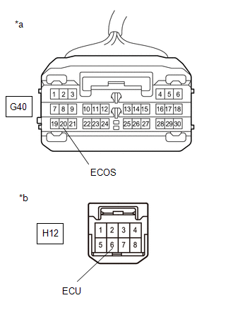
| 5. | CHECK HARNESS AND CONNECTOR (DRIVE MODE SELECT SWITCH (COMBINATION SWITCH ASSEMBLY) - BODY GROUND) |
(a) Disconnect the H12 drive mode select switch (combination switch assembly) connector.
| (b) Measure the resistance according to the value(s) in the table below. Standard Resistance:
|
|

(c) Reconnect the H12 drive mode select switch (combination switch assembly) connector.
| NG | | REPAIR OR REPLACE HARNESS OR CONNECTOR |
|
| 6. | CHECK HARNESS AND CONNECTOR (AIR CONDITIONING AMPLIFIER ASSEMBLY - DRIVE MODE SELECT SWITCH (COMBINATION SWITCH ASSEMBLY)) |
(a) Disconnect the G40 air conditioning amplifier assembly connector.
(b) Disconnect the H12 drive mode select switch (combination switch assembly) connector.
| (c) Measure the resistance according to the value(s) in the table below. Standard Resistance:
|
|
(d) Reconnect the H12 drive mode select switch (combination switch assembly) connector.
(e) Reconnect the G40 air conditioning amplifier assembly connector.
| OK | | REPLACE AIR CONDITIONING AMPLIFIER ASSEMBLY |
| NG | | REPAIR OR REPLACE HARNESS OR CONNECTOR |
READ NEXT:
 Indicator Circuit
DESCRIPTION In accordance with the shift lever position, each shift position indicator light will turn on. WIRING DIAGRAM PROCEDURE 1. CHECK SHIFT POSITION INDICATOR (a) Turn the power switc
ECU Power Source Circuit
DESCRIPTION If the power switch is on (IG), the hybrid vehicle control ECU applies current to the MREL terminal to turn the IGCT relay on. This supplies power to the +B1 and +B2 terminals. WIRING DIAG
Motor Resolver Circuit
DESCRIPTION The cause of this malfunction may be the motor resolver. Check the motor resolver internal resistance and the connection condition from the inverter to the resolver. Related Parts Check
SEE MORE:
Steering Position Sensor (B2414)
DESCRIPTION The headlight ECU sub-assembly LH receives steering angle signals from the steering sensor via CAN communication and performs light control. for LED Type Turn Signal Light DTC No. Detection Item DTC Detection Condition Trouble Area DTC Output from B2414 Steering Position
Dtc Check / Clear
DTC CHECK / CLEAR NOTICE: When the diagnosis system is changed from normal mode to check mode or vice versa, all DTCs and Freeze Frame Data recorded in normal mode are cleared. Before changing modes, always check and make a note of DTCs and Freeze Frame Data. HINT:
DTCs which are stored in the EC
