Lexus ES: ECU Power Source Circuit
DESCRIPTION
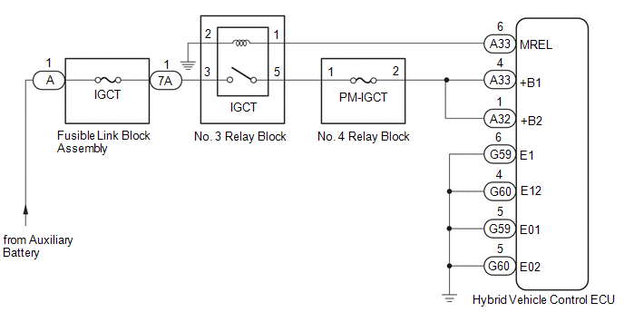
If the power switch is on (IG), the hybrid vehicle control ECU applies current to the MREL terminal to turn the IGCT relay on. This supplies power to the +B1 and +B2 terminals.
WIRING DIAGRAM
CAUTION / NOTICE / HINT
NOTICE:
After turning the power switch off, waiting time may be required before disconnecting the cable from the negative (-) auxiliary battery terminal. Therefore, make sure to read the disconnecting the cable from the negative (-) auxiliary battery terminal notices before proceeding with work.
Click here .gif)
PROCEDURE
| 1. | CHECK HYBRID VEHICLE CONTROL ECU (+B1, +B2 VOLTAGE) |
(a) Turn the power switch on (IG).
| (b) Measure the voltage according to the value(s) in the table below. Standard Voltage:
|
|
(c) Turn the power switch off.
| NG | .gif) | GO TO STEP 3 |
|
.gif)
| 2. | CHECK HARNESS AND CONNECTOR (HYBRID VEHICLE CONTROL ECU - BODY GROUND) |
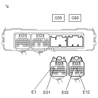
(a) Disconnect the G59 and G60 hybrid vehicle control ECU connectors.
| (b) Measure the resistance according to the value(s) in the table below. Standard Resistance:
|
|
(c) Reconnect the G59 and G60 hybrid vehicle control ECU connectors.
| OK | | GO TO PROBLEM SYMPTOMS TABLE |
| NG | | REPAIR OR REPLACE HARNESS OR CONNECTOR |
| 3. | CHECK HYBRID VEHICLE CONTROL ECU (MREL VOLTAGE) |
(a) Turn the power switch on (IG).
| (b) Measure the voltage according to the value(s) in the table below. Standard Voltage:
|
|
(c) Turn the power switch off.
| NG | | REPLACE HYBRID VEHICLE CONTROL ECU |
|
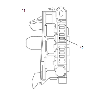
| 4. | CHECK FUSE (PM-IGCT) |
| (a) Remove the PM-IGCT fuse from the No. 4 relay block. |
|
(b) Measure the resistance according to the value(s) in the table below.
Standard Resistance:
| Tester Connection | Condition | Specified Condition |
|---|---|---|
| PM-IGCT fuse | Always | Below 1 Ω |
(c) Install the PM-IGCT fuse.
| NG | | GO TO STEP 12 |
|
| 5. | CHECK FUSIBLE LINK BLOCK ASSEMBLY (IGCT FUSE) |
(a) Disconnect the cable from the negative (-) auxiliary battery terminal.
(b) Disconnect the cable from the positive (+) auxiliary battery terminal.
| (c) Disconnect the 7A fusible link block assembly connector. |
|
.png)
| (d) Measure the resistance according to the value(s) in the table below. Standard Resistance:
|
|
.png)
(e) Reconnect the 7A fusible link block assembly connector.
(f) Reconnect the cable to the positive (+) auxiliary battery terminal.
(g) Reconnect the cable to the negative (-) auxiliary battery terminal.
| NG | | GO TO STEP 13 |
|
| 6. | INSPECT RELAY (IGCT) |
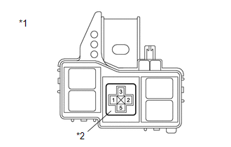
| (a) Remove the IGCT relay from the No. 3 relay block. |
|
.png)
| (b) Measure the resistance according to the value(s) in the table below. Standard Resistance:
|
|
.png)
(c) Install the IGCT relay.
| NG | | REPLACE RELAY (IGCT) |
|
| 7. | CHECK HARNESS AND CONNECTOR (NO. 4 RELAY BLOCK - HYBRID VEHICLE CONTROL ECU) |
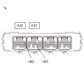
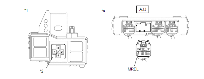
(a) Disconnect the A32 and A33 hybrid vehicle control ECU connectors.
(b) Remove the PM-IGCT fuse from the No. 4 relay block.
(c) Measure the resistance according to the value(s) in the table below.
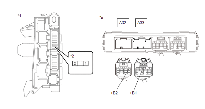
| *1 | No. 4 Relay Block | *2 | PM-IGCT Fuse Holder |
| *a | Rear view of wire harness connector (to Hybrid Vehicle Control ECU) | - | - |
Standard Resistance:
| Tester Connection | Condition | Specified Condition |
|---|---|---|
| A33-4 (+B1) - 2 (PM-IGCT fuse holder) | Always | Below 1 Ω |
| A32-1 (+B2) - 2 (PM-IGCT fuse holder) | Always | Below 1 Ω |
(d) Reconnect the A32 and A33 hybrid vehicle control ECU connectors.
(e) Install the PM-IGCT fuse.
| NG | | REPAIR OR REPLACE HARNESS OR CONNECTOR |
|
| 8. | CHECK HARNESS AND CONNECTOR (NO. 3 RELAY BLOCK - NO. 4 RELAY BLOCK) |
(a) Remove the IGCT relay from the No. 3 relay block.
(b) Remove the PM-IGCT fuse from the No. 4 relay block.
(c) Measure the resistance according to the value(s) in the table below.
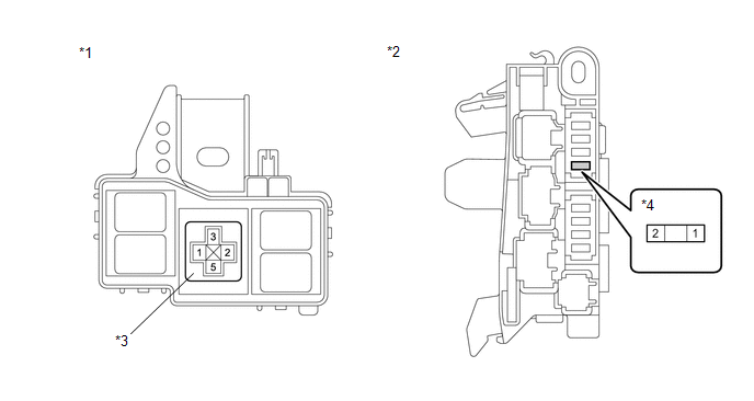
| *1 | No. 3 Relay Block | *2 | No. 4 Relay Block |
| *3 | IGCT Relay Holder | *4 | PM-IGCT Fuse Holder |
Standard Resistance:
| Tester Connection | Condition | Specified Condition |
|---|---|---|
| 5 (IGCT relay holder) - 1 (PM-IGCT fuse holder) | Always | Below 1 Ω |
(d) Install the PM-IGCT fuse.
(e) Install the IGCT relay.
| NG | | REPAIR OR REPLACE HARNESS OR CONNECTOR |
|
| 9. | CHECK HARNESS AND CONNECTOR (FUSIBLE LINK BLOCK ASSEMBLY - NO. 3 RELAY BLOCK) |
(a) Disconnect the 7A fusible link block assembly connector.
| (b) Remove the IGCT relay from the No. 3 relay block. |
|
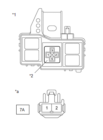
(c) Measure the resistance according to the value(s) in the table below.
Standard Resistance:
| Tester Connection | Condition | Specified Condition |
|---|---|---|
| 3 (IGCT relay holder) - 7A-1 | Always | Below 1 Ω |
(d) Install the IGCT relay.
(e) Reconnect the 7A fusible link block assembly connector.
| NG | | REPAIR OR REPLACE HARNESS OR CONNECTOR |
|
| 10. | CHECK HARNESS AND CONNECTOR (HYBRID VEHICLE CONTROL ECU - NO. 3 RELAY BLOCK) |
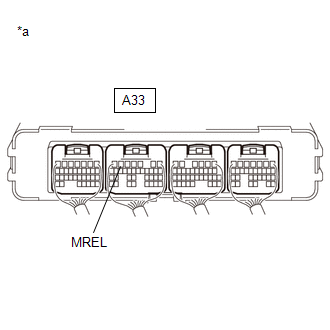
(a) Disconnect the A33 hybrid vehicle control ECU connector.
(b) Remove the IGCT relay from the No. 3 relay block.
(c) Measure the resistance according to the value(s) in the table below.
| *1 | No. 3 Relay Block | *2 | IGCT Relay Holder |
| *a | Rear view of wire harness connector (to Hybrid Vehicle Control ECU) | - | - |
Standard Resistance:
| Tester Connection | Condition | Specified Condition |
|---|---|---|
| A33-6 (MREL) - 1 (IGCT relay holder) | Always | Below 1 Ω |
| A33-6 (MREL) or 1 (IGCT relay holder) - Body ground and other terminals | Always | 10 kΩ or higher |
(d) Install the IGCT relay.
(e) Reconnect the A33 hybrid vehicle control ECU connector.
| NG | | REPAIR OR REPLACE HARNESS OR CONNECTOR |
|
| 11. | CHECK HARNESS AND CONNECTOR (NO. 3 RELAY BLOCK - BODY GROUND) |
(a) Remove the IGCT relay from the No. 3 relay block.
| (b) Measure the resistance according to the value(s) in the table below. Standard Resistance:
|
|
(c) Install the IGCT relay.
| OK | | CHECK FOR INTERMITTENT PROBLEMS |
| NG | | REPAIR OR REPLACE HARNESS OR CONNECTOR |
| 12. | CHECK HARNESS AND CONNECTOR (NO. 4 RELAY BLOCK - HYBRID VEHICLE CONTROL ECU) |
(a) Remove the PM-IGCT fuse from the No. 4 relay block.
(b) Disconnect the A32 and A33 hybrid vehicle control ECU connectors.
(c) Measure the resistance according to the value(s) in the table below.
| *1 | No. 4 Relay Block | *2 | PM-IGCT Fuse Holder |
| *a | Rear view of wire harness connector (to Hybrid Vehicle Control ECU) | - | - |
Standard Resistance:
| Tester Connection | Condition | Specified Condition |
|---|---|---|
| A33-4 (+B1) or 2 (PM-IGCT fuse holder) - Body ground and other terminals | Always | 10 kΩ or higher |
| A32-1 (+B2) or 2 (PM-IGCT fuse holder) - Body ground and other terminals | Always | 10 kΩ or higher |
(d) Reconnect the A32 and A33 hybrid vehicle control ECU connectors.
(e) Install the PM-IGCT fuse.
| OK | | REPLACE FUSE (PM-IGCT) |
| NG | | GO TO STEP 15 |
| 13. | CHECK HARNESS AND CONNECTOR (FUSIBLE LINK BLOCK ASSEMBLY - NO. 3 RELAY BLOCK) |
(a) Disconnect the 7A fusible link block assembly connector.
(b) Remove the IGCT relay from the No. 3 relay block.
| (c) Measure the resistance according to the value(s) in the table below. Standard Resistance:
|
|
(d) Install the IGCT relay.
(e) Reconnect the 7A fusible link block assembly connector.
| NG | | GO TO STEP 16 |
|
| 14. | CHECK HARNESS AND CONNECTOR (NO. 3 RELAY BLOCK - NO. 4 RELAY BLOCK) |
(a) Remove the IGCT relay from the No. 3 relay block.
(b) Remove the PM-IGCT fuse from the No. 4 relay block.
(c) Measure the resistance according to the value(s) in the table below.
| *1 | No. 3 Relay Block | *2 | No. 4 Relay Block |
| *3 | IGCT Relay Holder | *4 | PM-IGCT Fuse Holder |
Standard Resistance:
| Tester Connection | Condition | Specified Condition |
|---|---|---|
| 5 (IGCT relay holder) or 1 (PM-IGCT fuse holder) - Body ground and other terminals | Always | 10 kΩ or higher |
(d) Install the PM-IGCT fuse.
(e) Install the IGCT relay.
| OK | | REPLACE FUSIBLE LINK BLOCK ASSEMBLY (IGCT FUSE) |
| NG | | GO TO STEP 17 |
| 15. | REPAIR OR REPLACE HARNESS OR CONNECTOR |
| NEXT | | REPLACE FUSE (PM-IGCT) |
| 16. | REPAIR OR REPLACE HARNESS OR CONNECTOR |
| NEXT | | REPLACE FUSIBLE LINK BLOCK ASSEMBLY (IGCT FUSE) |
| 17. | REPAIR OR REPLACE HARNESS OR CONNECTOR |
| NEXT | | REPLACE FUSIBLE LINK BLOCK ASSEMBLY (IGCT FUSE) |
READ NEXT:
 Motor Resolver Circuit
DESCRIPTION The cause of this malfunction may be the motor resolver. Check the motor resolver internal resistance and the connection condition from the inverter to the resolver. Related Parts Check
Motor High-voltage Circuit
DESCRIPTION The cause of the malfunction may be the high-voltage circuit of the motor. Check the motor internal resistance and the connection condition of the high-voltage line between the inverter an
Generator Resolver Circuit
DESCRIPTION The cause of this malfunction may be the generator resolver. Check the generator resolver internal resistance and connection condition from the inverter to the resolver. Related Parts Chec
SEE MORE:
Replacement
REPLACEMENT
CAUTION / NOTICE / HINT
The necessary procedures (adjustment, calibration, initialization or registration)
that must be performed after parts are removed and installed, or replaced during
automatic transaxle fluid replacement are shown below.
Necessary Procedures After Parts Remov
Customize Parameters
CUSTOMIZE PARAMETERS CUSTOMIZE POWER WINDOW CONTROL SYSTEM HINT: The following items can be customized. NOTICE:
When the customer requests a change in a function, first make sure that the function can be customized.
Be sure to make a note of the current settings before customizing.
When troub
