Lexus ES: Parts Location
PARTS LOCATION
ILLUSTRATION
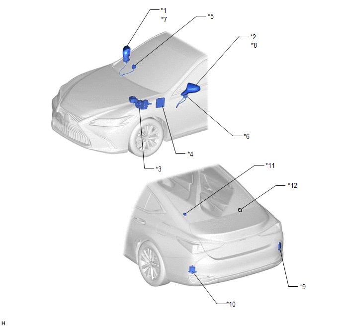
| *1 | OUTER REAR VIEW MIRROR ASSEMBLY RH | *2 | OUTER REAR VIEW MIRROR ASSEMBLY LH |
| *3 | BRAKE BOOSTER WITH MASTER CYLINDER ASSEMBLY - SKID CONTROL ECU | *4 | HYBRID VEHICLE CONTROL ECU |
| *5 | OUTER MIRROR CONTROL ECU ASSEMBLY RH | *6 | OUTER MIRROR CONTROL ECU ASSEMBLY LH |
| *7 | OUTER REAR VIEW MIRROR INDICATOR RH | *8 | OUTER REAR VIEW MIRROR INDICATOR LH |
| *9 | BLIND SPOT MONITOR SENSOR RH (MASTER) | *10 | BLIND SPOT MONITOR SENSOR LH (SLAVE) |
| *11 | RCTA BUZZER (BLIND SPOT MONITOR BUZZER) | *12 | No. 24 CAN JUNCTION CONNECTOR |
ILLUSTRATION
.png)
| *1 | STEERING PAD SWITCH ASSEMBLY | *2 | DLC3 |
| *3 | STEERING SENSOR | *4 | COMBINATION METER ASSEMBLY - MULTI-INFORMATION DISPLAY |
| *5 | INSTRUMENT PANEL JUNCTION BLOCK ASSEMBLY - ECU-IG1 NO. 4 FUSE - IG1-NO. 1 RELAY | *6 | MAIN BODY ECU (MULTIPLEX NETWORK BODY ECU) |
| *7 | AIRBAG SENSOR ASSEMBLY - YAW RATE AND ACCELERATION SENSOR | *8 | MULTI-DISPLAY ASSEMBLY |
| *9 | PARKING ASSIST ECU (w/ Panoramic View Monitor System) | - | - |
READ NEXT:
 Power Source Circuit
DESCRIPTION This circuit provides power to operate the blind spot monitor sensor. WIRING DIAGRAM CAUTION / NOTICE / HINT NOTICE: Inspect the fuses for circuits related to this system before performin
Precaution
PRECAUTION PRECAUTION FOR DISCONNECTING CABLE FROM NEGATIVE AUXILIARY BATTERY TERMINAL NOTICE: When disconnecting the cable from the negative (-) auxiliary battery terminal, initialize the following s
Problem Symptoms Table
PROBLEM SYMPTOMS TABLE HINT:
Use the table below to help determine the cause of problem symptoms. If multiple suspected areas are listed, the potential causes of the symptoms are listed in order of
SEE MORE:
Inspection
INSPECTION PROCEDURE 1. INSPECT CAMSHAFT TIMING GEAR BOLT (a) Check the stroke of the plunger in the center of the camshaft timing gear bolt. Standard Stroke: 2.2 mm (0.0866 in.) or more HINT: When pressing the plunger, there may be a stepped feeling. This is not a malfunction. If the result is
CAN Communication Failure (Message Registry) (U1000)
DESCRIPTION This DTC is stored when the rear television camera assembly judges that it has an internal CAN malfunction. DTC No. Detection Item DTC Detection Condition Trouble Area U1000 CAN Communication Failure (Message Registry) Can communication failure (message registry) Rear
