Lexus ES: Removal
REMOVAL
CAUTION / NOTICE / HINT
The necessary procedures (adjustment, calibration, initialization, or registration) that must be performed after parts are removed and installed, or replaced during outer rear view mirror assembly with cover removal/installation are shown below.
Necessary Procedure After Parts Removed/Installed/Replaced (for Gasoline Model)| Replaced Part or Performed Procedure | Necessary Procedure | Effect/Inoperative Function when Necessary Procedure not Performed | Link |
|---|---|---|---|
| Side television camera view adjustment | Panoramic view monitor system | |
| Replaced Part or Performed Procedure | Necessary Procedure | Effect/Inoperative Function when Necessary Procedure not Performed | Link |
|---|---|---|---|
| Side television camera view adjustment | Panoramic view monitor system | |
HINT:
- Use the same procedure for the RH side and LH side.
- The following procedure is for the LH side.
PROCEDURE
1. REMOVE NO. 2 DOOR TRIM PAD
Click here .gif)
2. REMOVE MULTIPLEX NETWORK MASTER SWITCH ASSEMBLY WITH FRONT DOOR UPPER ARMREST BASE PANEL (for Driver Side)
Click here
3. REMOVE POWER WINDOW REGULATOR SWITCH ASSEMBLY WITH FRONT DOOR UPPER ARMREST BASE PANEL (for Front Passenger Side)
Click here
4. REMOVE COURTESY LIGHT ASSEMBLY
Click here
5. REMOVE FRONT DOOR TRIM BOARD SUB-ASSEMBLY
Click here
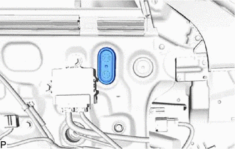
6. REMOVE HOLE PLUG
| (a) Remove the hole plug. |
|
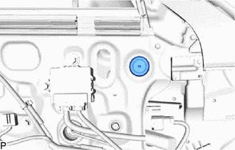
| (b) Remove the hole plug. |
|
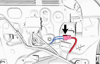
7. REMOVE OUTER MIRROR INSTALL HOLE COVER
(a) w/ Panoramic View Monitor System:
| (1) Disconnect the connector. |
|
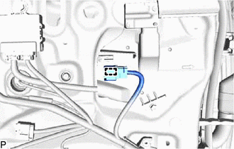
| (b) Disengage the clamp. |
|
| (c) Remove the screw. |
|
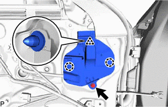
(d) Disengage the clip and 2 claws to remove the outer mirror install hole cover.
8. REMOVE OUTER REAR VIEW MIRROR ASSEMBLY
(a) Disconnect the connector.
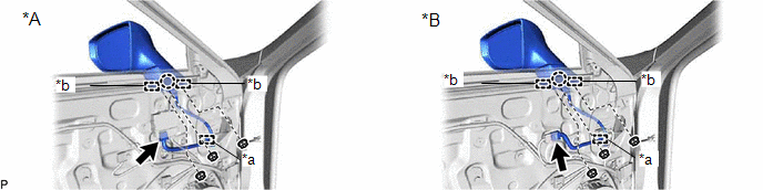
| *A | w/ Seat Memory Switch | *B | w/o Seat Memory Switch |
| *a | Clamp | *b | Guide |
(b) Disengage the clamp.
(c) Remove the 3 nuts.
(d) Disengage the claw and 2 guides and remove the outer rear view mirror assembly.
READ NEXT:
 Disassembly
DISASSEMBLY CAUTION / NOTICE / HINT HINT:
Use the same procedure for the RH side and LH side.
The following procedure is for the LH side.
PROCEDURE 1. REMOVE OUTER MIRROR Click here 2. REMO
Inspection
INSPECTION PROCEDURE 1. INSPECT OUTER REAR VIEW MIRROR ASSEMBLY RH (a) Check the operation of the mirror surface. NOTICE: If the mirror surface is fully turned to the right, left, upward or downward p
Reassembly
REASSEMBLY CAUTION / NOTICE / HINT HINT:
Use the same procedure for the RH side and LH side.
The following procedure is for the LH side.
PROCEDURE 1. INSTALL VISOR COVER ASSEMBLY Click here
SEE MORE:
Engine Oil Temperature Sensor Circuit Short to Ground (P019511)
DESCRIPTION The engine oil temperature sensor replaces the oil temperature with electrical signals and outputs them to the ECM. DTC No. Detection Item DTC Detection Condition Trouble Area MIL Memory Note P019511 Engine Oil Temperature Sensor Circuit Short to Ground The engine
Front Wiper Rubber
Components
COMPONENTS
ILLUSTRATION
*1
FRONT WIPER BLADE
*2
WIPER RUBBER
*3
FRONT WIPER RUBBER BACKING PLATE
-
-
Removal
REMOVAL
CAUTION / NOTICE / HINT
NOTICE:
Make sure to hold the f
