Lexus ES: Parts Location
Lexus ES (XZ10) Service Manual / Vehicle Exterior / Window / Glass / Windshield Deicer System (for Hv Model) / Parts Location
PARTS LOCATION
ILLUSTRATION
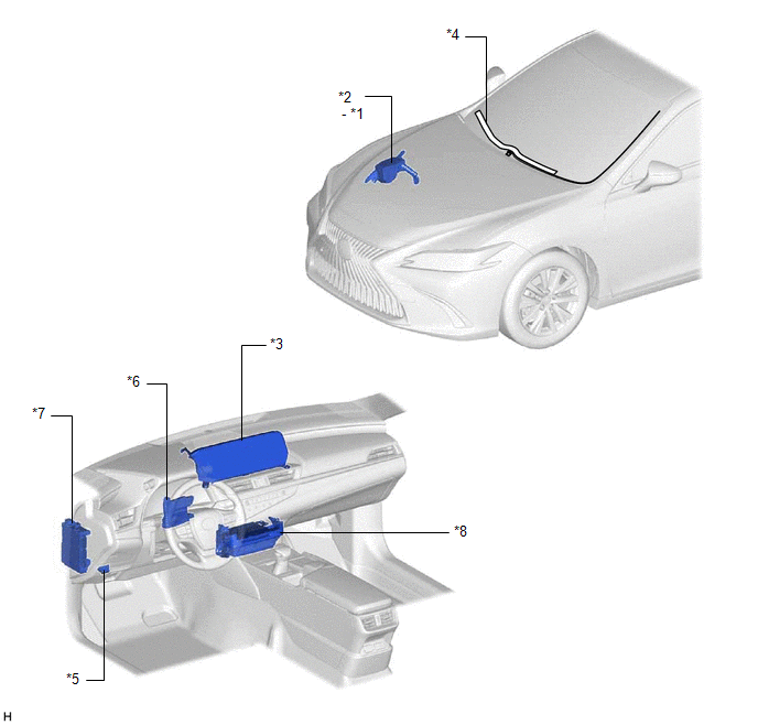
| *1 | DEICER RELAY | *2 | NO. 2 ENGINE ROOM RELAY BLOCK AND NO. 2 ENGINE ROOM JUNCTION BLOCK ASSEMBLY - DEICER FUSE |
| *3 | MULTI-DISPLAY ASSEMBLY - FRONT WIPER DEICER SWITCH | *4 | WINDSHIELD DEICER WIRE (WINDSHIELD GLASS) |
| *5 | DLC3 | *6 | AIR CONDITIONING AMPLIFIER ASSEMBLY |
| *7 | INSTRUMENT PANEL JUNCTION BLOCKASSEMBLY - ECU-IG2 NO. 3 FUSE | *8 | RADIO RECEIVER ASSEMBLY |
READ NEXT:
 System Diagram
SYSTEM DIAGRAM Sender Receiver Signal Communication Method Radio Receiver Assembly Air Conditioning Amplifier Assembly Front wiper deicer switch signal CAN
System Description
SYSTEM DESCRIPTION GENERAL The windshield deicer system uses thin heater wires attached to the inside of the windshield glass to help deice the window surface more quickly. An indicator light illumina
How To Proceed With Troubleshooting
CAUTION / NOTICE / HINT HINT:
Use the following procedure to troubleshoot the windshield deicer system.
*: Use the Techstream.
PROCEDURE 1. VEHICLE BROUGHT TO WORKSHOP
NEXT
SEE MORE:
Back Camera Internal Circuit (C2A63)
DESCRIPTION This DTC is stored when the parking assist ECU detects a signal indicating a malfunction in the rear television camera assembly via CAN communication. DTC No. Detection Item DTC Detection Condition Trouble Area C2A63 Back Camera Internal Circuit A signal indicating a mal
Parts Location
PARTS LOCATION ILLUSTRATION *1 CANISTER (CHARCOAL CANISTER ASSEMBLY) *2 EGR VALVE ASSEMBLY *3 FUEL TANK CAP ASSEMBLY *4 FUEL VAPOR CONTAINMENT VALVE (FUEL TANK SOLENOID MAIN VALVE ASSEMBLY) *5 PCV VALVE (VENTILATION VALVE SUB-ASSEMBLY) *6 PURGE VALVE (PURGE VSV) *7
© 2016-2026 Copyright www.lexguide.net
